Output circuit, temperature switch ic, and battery pack

a technology of output circuit and temperature switch, applied in the field of output circuit, can solve problems such as large area of output circuit, and achieve the effect of reducing area and restricting unstable outputs

Active Publication Date: 2012-07-26
ABLIC INC
View PDF13 Cites 4 Cited by
  • Summary
  • Abstract
  • Description
  • Claims
  • Application Information

AI Technical Summary

Benefits of technology

[0014]The output circuit according to the present invention is configured such that, if a power supply voltage is lower than an operating voltage of the circuit, then the operation of the inverter is interrupted and the gate of an output driver is controlled to turn it off. Hence, a large MOS transistor is no longer required to be provided between the source of the output driver and a power source. This arrangement enables the output circuit to restrain unstable outputs even when the power supply voltage is lower than the operating voltage and to achieve a reduced area.

Problems solved by technology

The conventional output circuit has been posing a problem that the large size of the NMOS transistor 94 inconveniently leads to a large area of the output circuit.

Method used


Image

  • Output circuit, temperature switch ic, and battery pack
  • Output circuit, temperature switch ic, and battery pack
  • Output circuit, temperature switch ic, and battery pack

Examples


Embodiment Construction

[0022]Embodiments of the present invention will be described below with reference to the accompanying drawings.

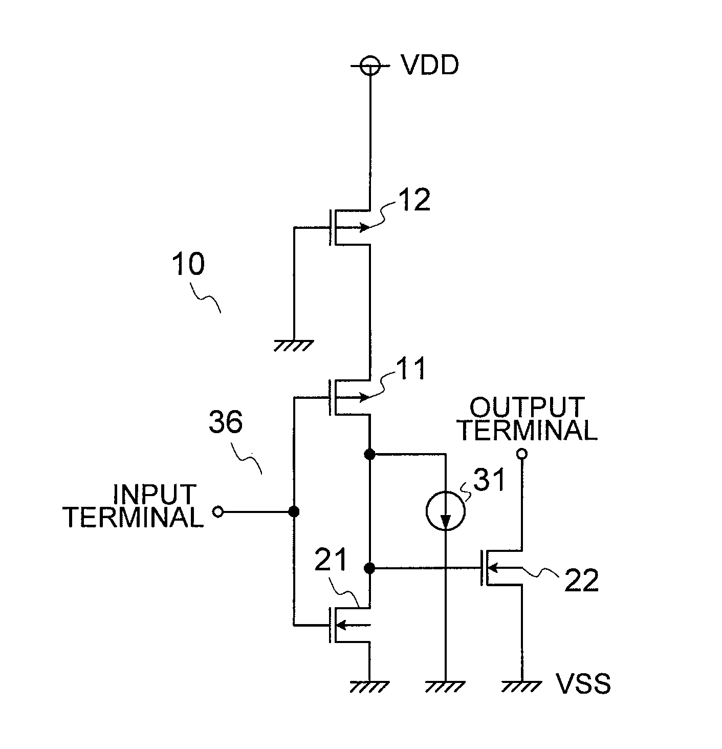
[0023]FIG. 1 is a circuit diagram illustrating an output circuit according to an embodiment of the present invention.

[0024]An output circuit 10 has PMOS transistors 11 and 12, NMOS transistors 21 and 22, and a current source 31.

[0025]The PMOS transistor 11 has the gate thereof connected to the input terminal of the output circuit 10, the source thereof connected to the drain of the PMOS transistor 12, and the drain thereof connected to the gate of the NMOS transistor 22. The NMOS transistor 21 has the gate thereof connected to the input terminal of the output circuit, the source thereof connected to an earth terminal (a power supply terminal at an earth voltage side), and the drain thereof connected to the gate of the NMOS transistor 22. The PMOS transistor 12 has the gate thereof connected to the earth terminal and the source thereof connected to a supply terminal (the pow...


PUM


Abstract

An output circuit has a smaller area and restrains outputs from becoming unstable even if a power supply voltage is lower than an operating voltage. A supply terminal of an inverter circuit is provided with switch circuit, and the switch circuit stops the operation of the inverter circuit when the power supply voltage is lower than the operating voltage of the circuit. Further, the output terminal of the inverter circuit is provided with a current source to fix the output to the power supply voltage when the operation of the inverter circuit is stopped.

Description

RELATED APPLICATIONS[0001]This application claims priority under 35 U.S.C. §119 to Japanese Patent Application No. 2011-013326 filed on Jan. 25, 2011, the entire content of which is hereby incorporated by reference.BACKGROUND OF THE INVENTION[0002]1. Field of the Invention[0003]The present invention relates to an output circuit, the output of one end of which has high impedance and, more particularly, to an output circuit which stably operates when a power supply voltage is low. The present invention further relates to a temperature switch IC and a battery pack, each of which is provided with the aforementioned output circuit.[0004]2. Description of the Related Art[0005]The following will describe a conventional output circuit. FIG. 7 is a circuit diagram illustrating a conventional output circuit.[0006]The conventional output circuit includes an inverter 97 connected to an input terminal, an NMOS transistor 93, which is an output driver, a diode-connected NMOS transistor 95 and a c...

Claims


Application Information

Patent Timeline
Patent Type & Authority Applications(United States)
IPC IPC(8): H02J7/00H03K3/00
CPCH02J7/0031H03K17/20H02J7/047H03K19/0013H03K19/018521H03K19/00361H02J7/04H02J7/007194A63B67/045A63B71/04A63B2208/12
Inventor MITANI, MASAHIROHIRAOKA, NAOHIROSUGIURA, MASAKAZUIGARASHI, ATSUSHI
Owner ABLIC INC
Why Eureka
Try Eureka