Method and device for sending and receiving a reference signal

a reference signal and method technology, applied in multiplex communication, frequency-division multiplex, wireless commuication services, etc., can solve the problems of limited application to real systems, channel environments that suffer from frequent changes, and low quality data services. achieve the effect of improving communication efficiency, reducing scheduling delay in transmission apparatus, and improving channel estimation performance of subframes

Active Publication Date: 2012-07-26
SAMSUNG ELECTRONICS CO LTD
View PDF6 Cites 5 Cited by
  • Summary
  • Abstract
  • Description
  • Claims
  • Application Information

AI Technical Summary

Benefits of technology

[0017]The reference signal transmission / reception method and apparatus according to the present invention is capable of improving channel estimation performance of subframe in a radio communication system. As a consequence, it is possible to reduce scheduling delay in the transmission apparatus of the radio communication system. Also, it is possible to improve the communication efficiency in the radio communication system.

Problems solved by technology

The origins of multicarrier modulation scheme started in the late 1950's with the microwave radio for military communication purpose, and OFDM using orthogonal overlapping multiple subcarriers has been developed in 1970's but limited in applying to the real systems due to the difficult of implementing orthogonal modulations between multiple carriers.
In wireless communications, high-speed, high-quality data services are generally hindered by the channel environments.
In wireless communications, the channel environments suffer from frequent changes not only due to additive white Gaussian noise (AWGN) but also power variation of received signals, caused by a fading phenomenon, shadowing, a Doppler effect brought by movement of a terminal and a frequent change in a velocity of the terminal, interference by other users or multipath signals, etc.

Method used

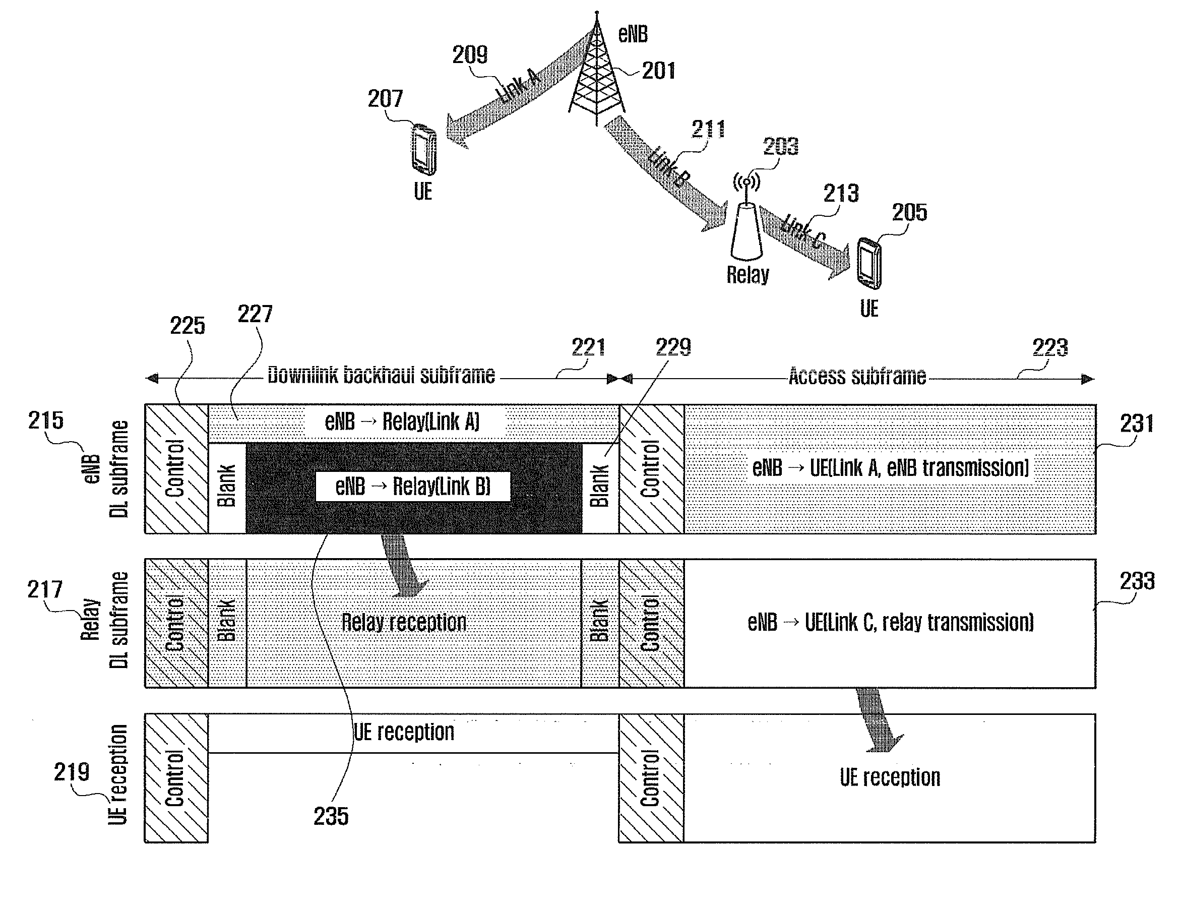
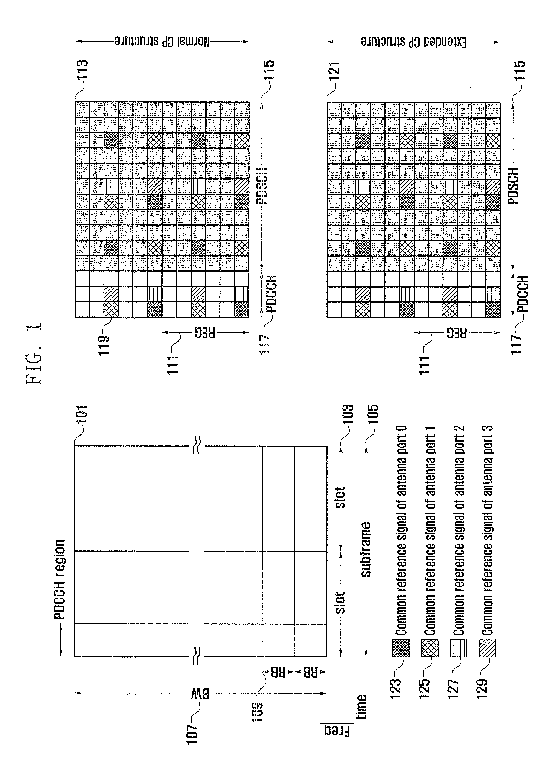
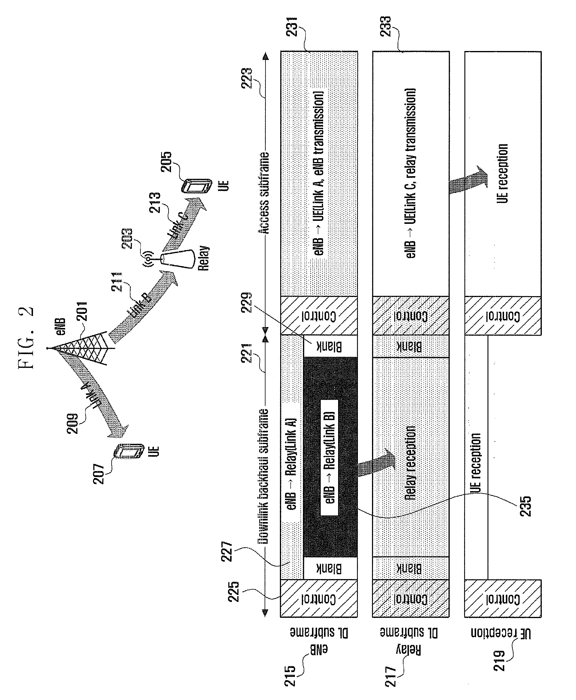

Image

  • Method and device for sending and receiving a reference signal
  • Method and device for sending and receiving a reference signal
  • Method and device for sending and receiving a reference signal

Examples


first embodiment

[0064]FIG. 5 is a diagram illustrating the structure of a relay backhaul reference signal according to the first embodiment of the present invention. Referring to FIG. 5, the first embodiment of the present invention proposes a method for grouping the relays having high correlation geographically and spatially in the cell, selecting a precoding to be applied to the group, multiplexing the relay control channels in the group, and transmitting group-specific dedicated reference signal. Meanwhile, since the data channels transmitted to the relays are not multiplexed, relay-specific dedicated reference signals are transmitted. This method is characterized in that the precoding for the control channel and the precoding for the data channel differ from each other.

[0065]Referring to FIG. 5, the relays A-1 and A-2 are highly correlated geographically or spatially, and the relays B-1 and B2 are highly correlated geographically or spatially. Accordingly, the eNB categories the relays A-1 and ...

second embodiment

[0074]FIG. 8 is a flowchart illustrating a relay control channel multiplexing method proposed in the second embodiment of the present invention. The control channel resource allocation according to the second embodiment is identical with that of the first embodiment.

[0075]Referring to FIG. 8, the method proposed in the second embodiment of the present invention is to transmit the common reference signal (CRS) in the relay control channel region through additional antenna ports. This method is of operating differently according to the number of transmit antennas in such a manner that the legacy subframe and common reference signal are used for the case where the number of antennas is equal to or less than 2 and additional common reference signals for the antenna ports 2 and 3 are transmitted in the relay control channel region for the case where the number of antennas is greater than 2. Since the common reference signal is not transmitted in the entire band in case of the subframe de...

third embodiment

[0085]FIG. 11 is a diagram illustrating a relay reference signal configuration method proposed in the third embodiment of the present invention.

[0086]The method proposed in the third embodiment is of using the relay-specific dedicated reference signal that can be applied to both the control and data channels. This method takes the influence of the multiplexed resource locations arranged randomly when a plurality of relay control channels are multiplexed in the same RB as denoted by reference number 425 of FIG. 4. Although possible to transmit signals in a dedicated pattern when the locations of the resource are fixed, it is difficult to guarantee the channel estimation performance with one pattern when the resource location varies. This embodiment proposes a method for configuring dedicated reference signal that is capable of performing channel estimation even when the resource allocation region varies. In order to accomplish the purpose, it is necessary to reserve a part of the all...


PUM


Abstract

The present invention relates to a method for sending and receiving a reference signal for a backhaul subframe in a wireless communication system in which a relay is present and also to a device therefor, constituted in such a way that common reference signals for a plurality of receiving devices and reference signals dedicated to separate receiving devices are allocated dispersed in a subframe, and the common reference signals and the dedicated reference signals are generated and are sent and received via the subframe. The present invention can improve the channel estimation performance for subframes in a wireless communication system. In this way, communications efficiency in wireless communication systems can be improved.

Description

BACKGROUND OF THE INVENTION[0001]1. Field of the Invention[0002]The present invention relates to a method and apparatus for configuring Reference Signal (RS) to be transmitted by a relay through wireless backhaul in a Orthogonal Frequency Division Multiplexing (OFDM) system using multiple carriers.[0003]2. Description of the Related Art[0004]OFDM is a transmission technique for transmitting data using multiple carriers, i.e. multicarrier data transmission technique which parallelizes the serial input stream into parallel data streams and modulates the data streams onto the orthogonal multiple carriers, i.e. sub-carrier channels.[0005]The origins of multicarrier modulation scheme started in the late 1950's with the microwave radio for military communication purpose, and OFDM using orthogonal overlapping multiple subcarriers has been developed in 1970's but limited in applying to the real systems due to the difficult of implementing orthogonal modulations between multiple carriers. Wi...

Claims


Application Information

Patent Timeline
Patent Type & Authority Applications(United States)
IPC IPC(8): H04W72/04H04W88/04
CPCH04L5/005H04L5/0051H04L5/0023H04L5/0069H04L5/0048H04L5/0032H04L5/0041H04L27/2613H04W72/23H04W88/08
Inventor JI, HYOUNG-JUCHO, JOON-YOUNGLEE, JUN-HO
Owner SAMSUNG ELECTRONICS CO LTD
Why Eureka
Try Eureka