Method and apparatus for obtaining precoding matrix indicator

a matrix indicator and precoding technology, applied in the field of communication technologies, can solve the problem of low accuracy of the fed back pmi, and achieve the effect of reducing overhead and improving feedback accuracy

Active Publication Date: 2012-07-26
HUAWEI TECH CO LTD
View PDF2 Cites 24 Cited by
  • Summary
  • Abstract
  • Description
  • Claims
  • Application Information

AI Technical Summary

Benefits of technology

[0007]To improve accuracy of feedback during feeding back a PMI, embodiments of the present disclosure provide a method and an apparatus for obtaining a precoding matrix indicator. The technical solutions are as follows:
[0025]The differential PMI is obtained according to the channel information, the differential PMI is used for feedback, and the information that already exists in the channel may be used, which not only reduces an overhead, but also makes full use of a correlation of a channel between a frequency domain and a time domain, thus improving the feedback accuracy.

Problems solved by technology

However, in the process of implementing the present disclosure, the inventor finds at least the following problems in the prior art:
The existing 3GPP LTE R8 system is primarily designed for SU-MIMO (Single User MIMO, single-user MIMO) and employs a fixed codebook, and the fed back PMI has low accuracy.

Method used


Image

  • Method and apparatus for obtaining precoding matrix indicator
  • Method and apparatus for obtaining precoding matrix indicator
  • Method and apparatus for obtaining precoding matrix indicator

Examples


embodiment 1

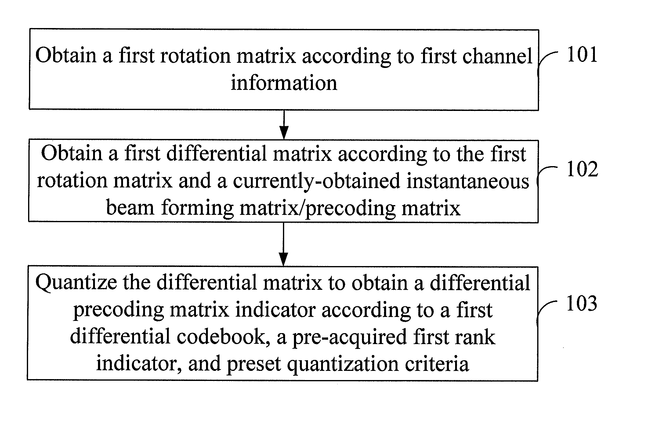
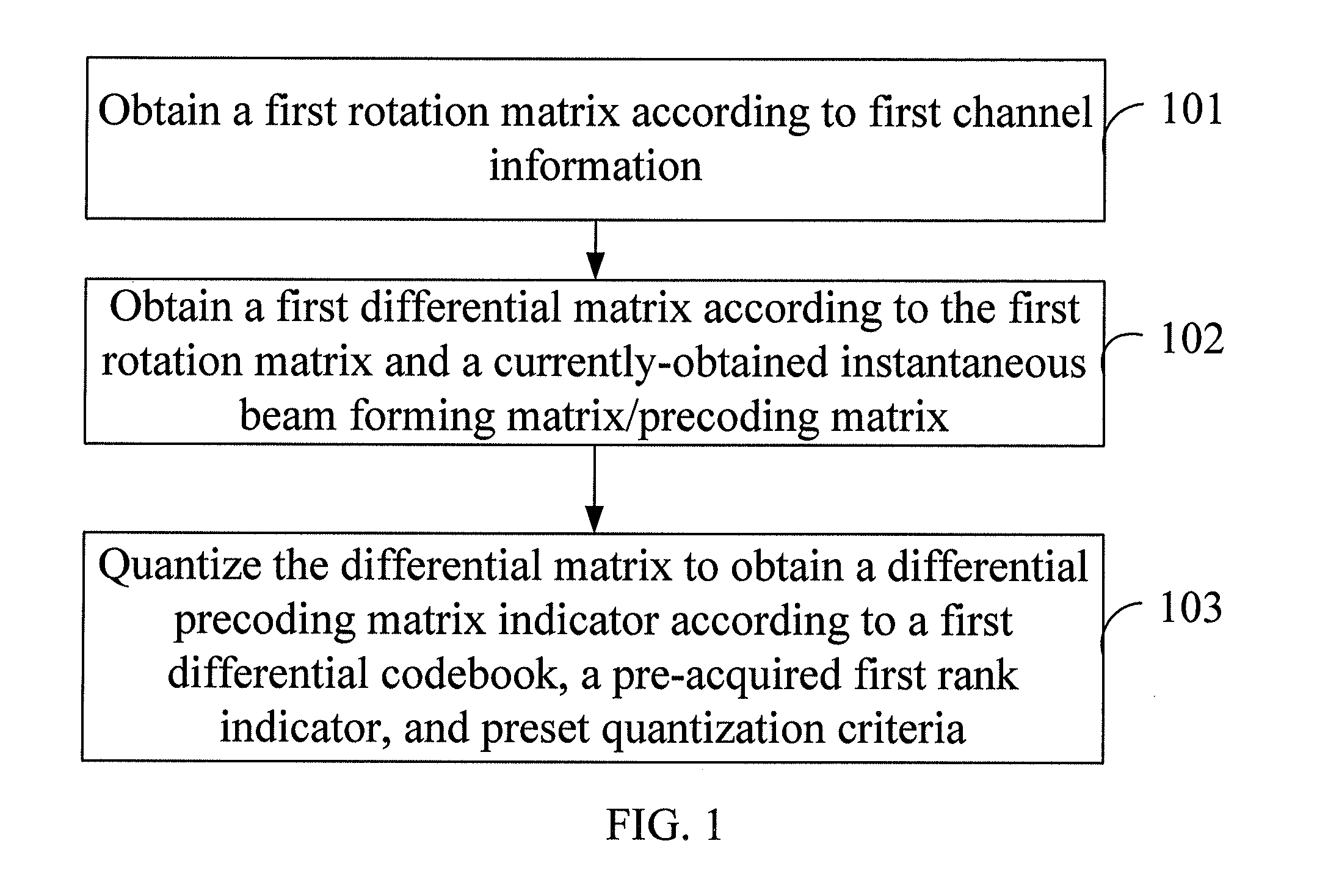
[0035]An embodiment of the present disclosure provides a method for obtaining a precoding matrix indicator. As shown in FIG. 1, the method includes:

[0036]101. Obtain a first rotation matrix according to first channel information.

[0037]102. Obtain a first differential matrix according to the first rotation matrix and a currently-obtained instantaneous beam forming matrix / precoding matrix.

[0038]103. Quantize, according to a first differential codebook, a pre-acquired first rank indicator, and preset quantization criteria, the first differential matrix to obtain a differential precoding matrix indicator.

[0039]When the first channel information is a first long-term channel covariance matrix, the obtaining the first rotation matrix according to the first channel information may include:

[0040]decomposing an eigenvalue of the first long-term channel covariance matrix to obtain a characteristic matrix of the first long-term channel covariance matrix, where the first long-term channel covari...

embodiment 2

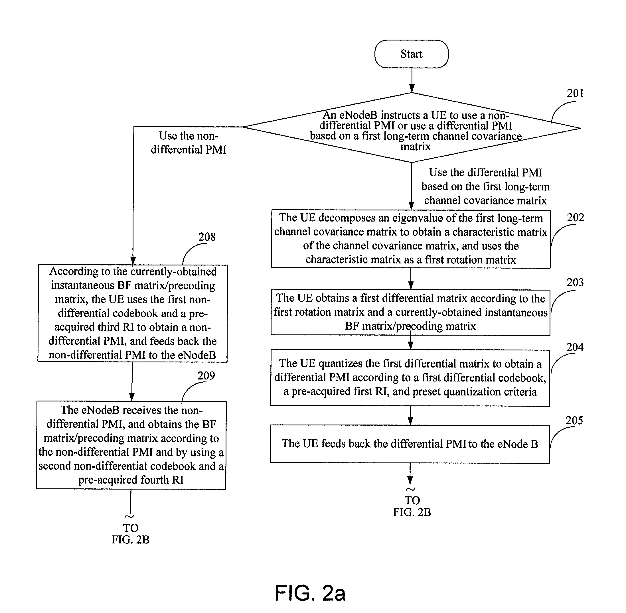
[0073]An embodiment of the present disclosure provides a method for obtaining a precoding matrix indicator. The method performs feedback by using a differential PMI based on a long-term channel covariance matrix. The following takes the downlink (namely, an eNode B sends data to a UE, and the UE feeds back a precoding matrix indicator to the eNode B) as an example for description. As shown in FIG. 2, the method includes:

[0074]201. An eNode B instructs a UE to use a non-differential PMI or a differential PMI based on a first long-term channel covariance matrix RUE for feedback. If the eNode B instructs the UE to use the non-differential PMI for feedback, step 208 is executed; if the eNode B instructs the UE to use the differential PMI based on the first long-term channel covariance matrix RUE for feedback, step 202 is executed.

[0075]For example, the eNode B may instruct the UE through high-layer signaling or a downlink physical control channel. Moreover, different identifiers may be ...

embodiment 3

[0110]An embodiment of the present disclosure provides a method for obtaining a precoding matrix indicator. The method performs feedback by using a differential PMI based on a reference PMI (expressed by PMIref). The following takes the uplink (namely, a UE sends data to an eNode B, and the eNode B feeds back a PMI to the UE) as an example for description. As shown in FIG. 3, the method includes:

[0111]301. An eNodeB determines whether to use a non-differential PMI or a differential PMI based on a reference PMIref for feedback, and notifies a UE. If the eNode B instructs the UE to use the non-differential PMI for feedback, step 308 is executed; if the eNode B instructs the UE to use the differential PMI based on the reference PMIref for feedback, step 302 is executed.

[0112]The reference PMIref may be: A non-differential broadband PMI or a non-differential neighboring sub-band PMI, which is used by the UE as instructed by the eNode B recently, may be used as the reference PMIref; or a...


PUM


Abstract

The present disclosure discloses a method and an apparatus for obtaining a precoding matrix indicator, and relates to the field of communication technologies. The method includes: obtaining a first rotation matrix according to first channel information; obtaining a first differential matrix according to the first rotation matrix and a currently-obtained instantaneous beam forming matrix / precoding matrix; and quantizing, according to a first differential codebook, a pre-acquired first rank indicator, and preset quantization criteria, the first differential matrix to obtain a differential precoding matrix indicator. The apparatus includes: a first rotation matrix obtaining module, a first differential matrix obtaining module, and a differential precoding matrix indicator obtaining module. In the present disclosure, the differential PMI is obtained according to the channel information, and the differential PMI is used for feedback, which not only reduces an overhead, but also improves feedback accuracy.

Description

CROSS-REFERENCE TO RELATED APPLICATIONS[0001]This application is a continuation of International Application No. PCT / CN2010 / 077545, filed on Sep. 30, 2010, which claims priority to Chinese Patent Application No. 200910235286.0, filed on Sep. 30, 2009, both of which are hereby incorporated by reference in their entireties.FIELD OF THE INVENTION[0002]The present disclosure relates to the field of communication technologies, and in particular, to a method and an apparatus for obtaining a precoding matrix indicator.BACKGROUND OF THE INVENTION[0003]With the continuous development of communication technologies, in a MIMO (Multiple Input Multiple Output, multiple input multiple output) wireless system, a data sender (such as an eNode B (evolved Node B, evolved Node B)) may obtain a BF (Beam Forming, beam forming) matrix / precoding matrix according to a pre-acquired RI (Rank Indicator, rank indicator) and a PMI (Precoding Matrix Indicator, precoding matrix indicator) fed back by a data recei...

Claims


Application Information

Patent Timeline
Patent Type & Authority Applications(United States)
IPC IPC(8): H04L25/49H04B7/02
CPCH04B7/0626H04B7/0639H04B7/0663H04B7/065H04B7/0641
Inventor WANG, JIANGUOZHOU, YONGXING
Owner HUAWEI TECH CO LTD
Why Eureka
Try Eureka