Modular drill with diamond cutting edges

Active Publication Date: 2012-07-26
KENNAMETAL INC
View PDF15 Cites 11 Cited by
  • Summary
  • Abstract
  • Description
  • Claims
  • Application Information

AI Technical Summary

Benefits of technology

[0010]A method of machining GFRP (glass fiber reinforced plastics) or fiberglass workpiece materials is also described. The method uses a modular drill as just described. The method comprises the steps of posi

Problems solved by technology

However, while this configuration may be suitable for some materials, the applicants have found that such a configuration is undesirable when machining materials such as fiberglass.
For different reasons, these same inserts are not suitable for machining titanium.
In particular, titanium is known for its toughness and typical cemented carbide inserts do not have the properties necessary for machining this material.
However, this design is not well suited for machining fiberglass because of abrasive wear and

Method used


Image

  • Modular drill with diamond cutting edges
  • Modular drill with diamond cutting edges
  • Modular drill with diamond cutting edges

Examples


Embodiment Construction

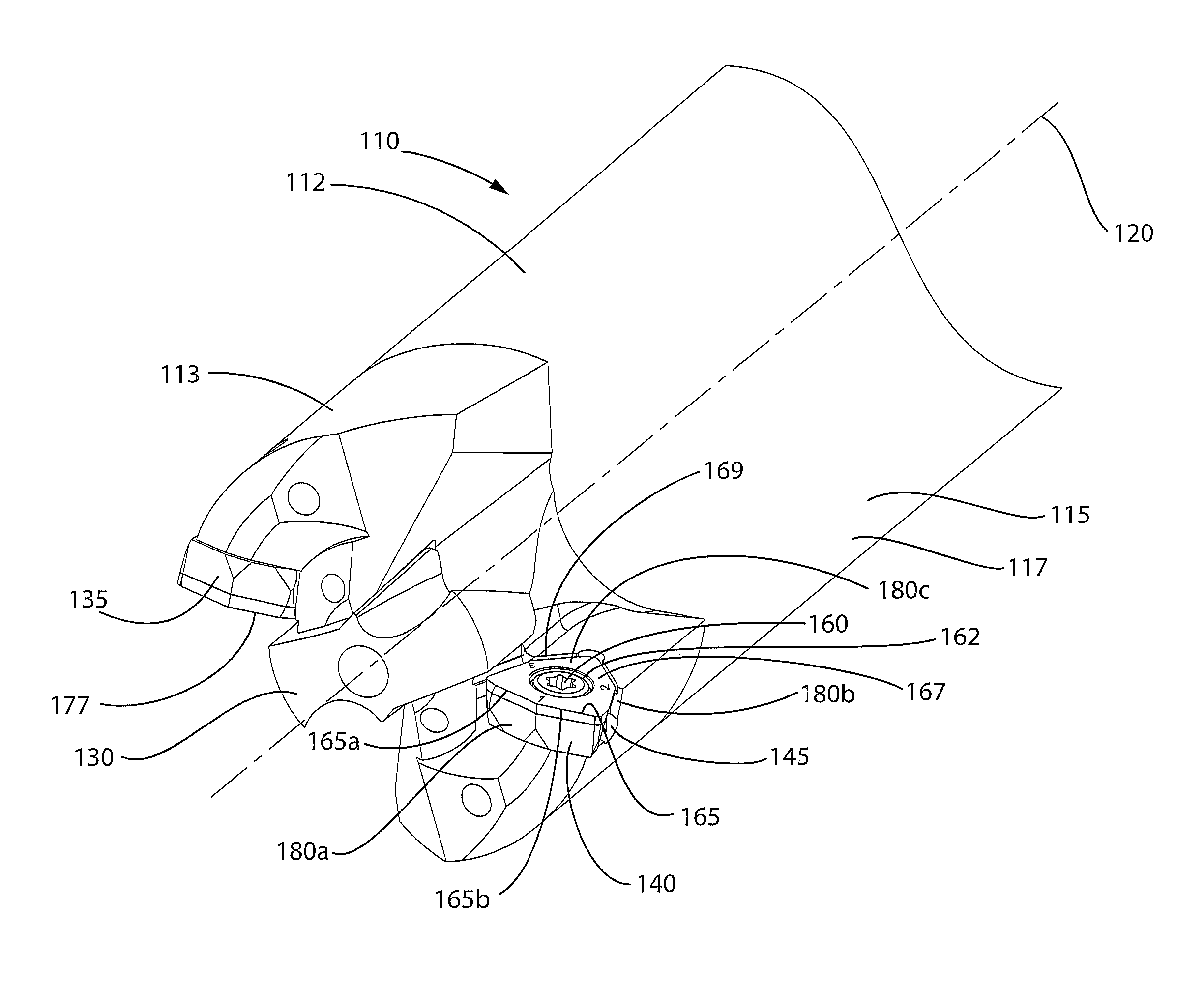
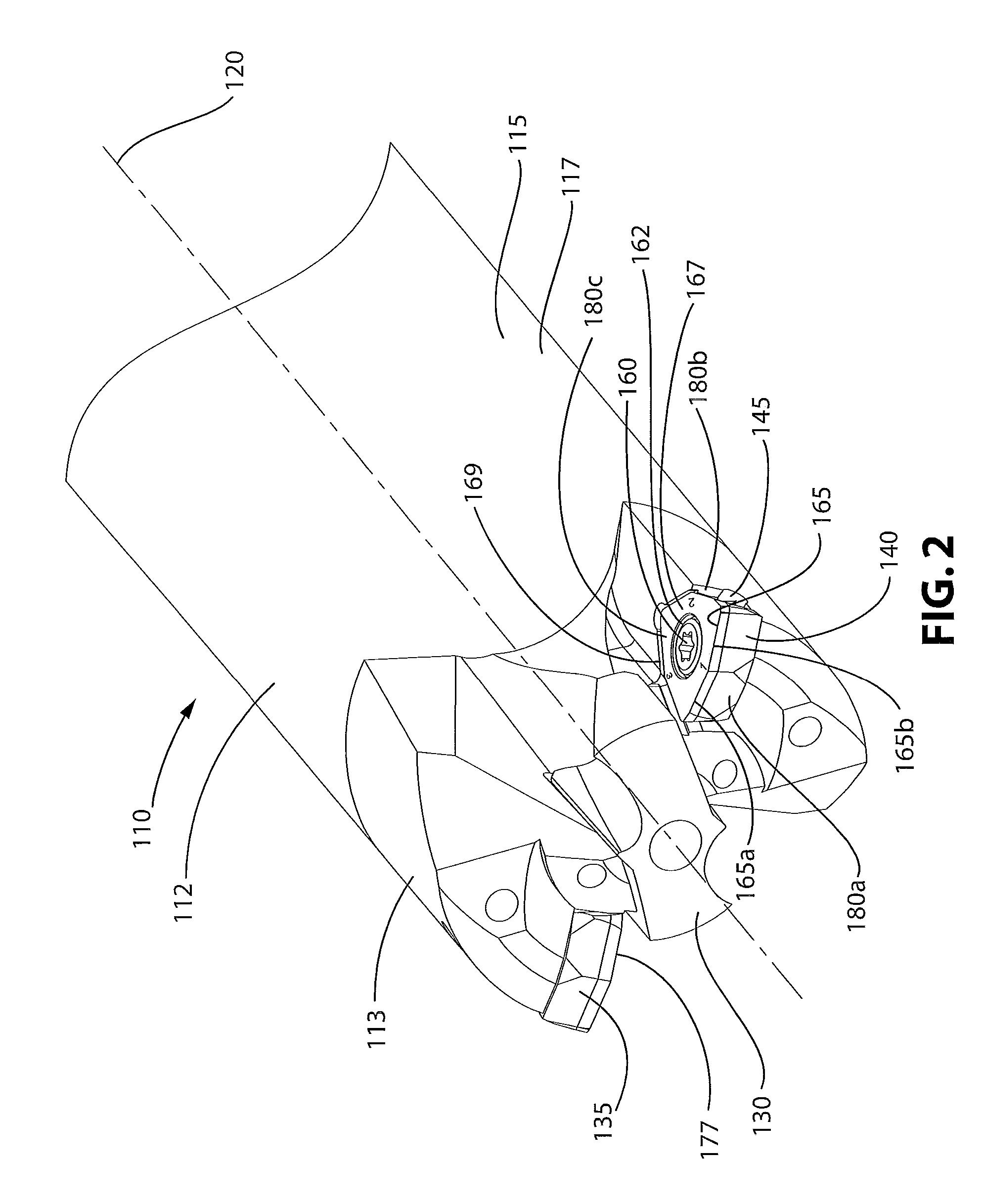
[0018]FIG. 2 illustrates a perspective view of a modular drill very similar to that illustrated in FIG. 1, with the exception that the operative cutting edge 165 of the outboard insert 140 has a diamond surface. For convenience, the reference numbers will be incremented by 100 for comparable parts of FIG. 2 originally described with respect to FIG. 1.

[0019]The modular drill 110 includes a second outboard insert 135 identical to insert 140 For convenience; only insert 140 will be described with the understanding that the same features are applicable to insert 135.

[0020]The description of the perspective drawing of the modular drill 110 shown in FIG. 2 will be further illustrated with the end view found in FIG. 3 and the side view found in FIG. 4.

[0021]FIGS. 2-4 illustrate a modular drill 110 for machining applications, whereby the modular drill 110 has a generally cylindrical body or shank 115 with a peripheral wall 117 about a central longitudinal axis 120. The body 112 has an upper...


PUM

PropertyMeasurementUnit
Shapeaaaaaaaaaa

Abstract

A modular drill for machining applications includes a central pilot drill made of cemented carbide and outboard radial inserts having cutting edges with a diamond surface. Additionally, the diamond surface associated with the cutting edges includes indicia identifying each cutting edge, such that indexing of the inserts is made easier. To ensure the indicia withstands the harsh machining environment, the indicia is laser etched onto the diamond surface of the insert

Description

BACKGROUND OF THE INVENTION[0001]1. Field of the Invention[0002]The invention relates to a modular drill with indexable cutting inserts having diamond cutting edges.[0003]2. Background of the Invention[0004]A modular drill is a drill consisting of interchangeable and disposable tips mechanically attached to a drill body. FIG. 1 illustrates such a modular drill 10 having a shank 15 extending along a longitudinal axis 20. The front end 25 of the drill 10 is moved axially along the longitudinal axis 20 such that a central pilot drill 30 and outboard inserts 35, 40 engage a workpiece and produce a hole extending therethrough. Typically, such modular drills have utilized a central pilot drill 30 comprised of cemented carbide and the outboard inserts 35, 40 also comprised of cemented carbide, which may or may not have coatings thereupon. However, while this configuration may be suitable for some materials, the applicants have found that such a configuration is undesirable when machining m...

Claims


Application Information

Patent Timeline
IPC IPC(8): B23B27/20B23B27/16B23B35/00B23B51/00
CPCB23B51/048B23B2222/88B23B2226/27B23B2226/315B23B2251/60B23B2260/104Y10T408/04Y10T408/906Y10T407/23Y10T408/88Y10T408/81Y10T408/21Y10T408/78B23B2200/0419B23B51/00B23B51/02
Inventor REINER, KENT L.CHESNEY, DAN ELWYNPRASAD, JAI
Owner KENNAMETAL INC
Why Eureka
Try Eureka