Specular coatings for composite structures

a composite structure and coating technology, applied in the direction of moulds, synthetic resin layered products, packaging, etc., can solve the problems of aluminum panels that were previously successful with high thermal expansion, low mass and achieve the effect of low mass, low thermal expansion, and low thermal expansion

Inactive Publication Date: 2012-08-02
NASA
View PDF9 Cites 25 Cited by
  • Summary
  • Abstract
  • Description
  • Claims
  • Application Information

AI Technical Summary

Benefits of technology

[0012]In the following description, certain aspects and embodiments of the present invention will become evident. It should be understood that the invention, in its broadest sense, could be practiced without having one or more features of these aspects and embodiments. It should also be understood that these embodiments are merely exemplary.

Problems solved by technology

Mass constraints for these missions have driven the use of low mass, high stiffness composite sandwich panels in place of the more traditional aluminum panels.
These composite materials may be composed of multiple plies of either fiberglass or carbon fibers in an epoxy matrix sandwiched with honeycomb that results in a very low thermal expansion.
Coating processes and materials that were previously successful with high thermal expansion aluminum panels do not work well with the newer low expansion composite structures.
Conventional methods exist for bonding materials, but such conventional methods do not reliably maintain attachment between dissimilar materials when exposed to substantial thermal or pressure variations, low pressure / vacuum or other stresses that tend to separate the bonded materials.
However, tests to demonstrate this on carbon fiber composite panels have shown that the high differential thermal coefficients of expansion between the lacquer and the composite panel showed cracks in the lacquer that increased in number and depth with thermal cycling to the point of breaking apart the fibers in the first ply of the composite face sheet.
This can be acceptable where the specularity requirement is less than 90%, but may not be suitable when higher specularity is required.
However, when applied to carbon fiber face sheets, the aluminum film can be destroyed by galvanic corrosion between aluminum and small areas of exposed carbon fiber.
This method is not easily repeatable and can be very expensive.
In testing this method, sometimes all or part of the aluminum stuck to the glass of the tool plate, leaving blank spots on the panel.
This sometimes resulted in the entire layer peeling off during thermal cycling.
With this process, if the coating process was not successful, the panel had to be scrapped, as there was no way to remove the epoxy layer without damaging the face sheet.
While the pressure sensitive adhesive is capable of withstanding the vacuum, it is temperature limited by the softening point or the glass transition temperature (Tg) of the adhesive.
The change in morphology caused by the bubbles or the blisters is unacceptable for any lightweight structure requiring a thermally stable coating that does not delaminate, blister, or peel, such as for solar arrays.
Conventional methods to adhere specular or RF reflective coatings to spacecraft structures thus have been found to delaminate, blister, or peel when exposed to the extreme conditions of space, which can reduce the specularity or RF reflectiveness of the coating and undesirably alter the thermal or RF properties of the structure / coating.

Method used


Image

  • Specular coatings for composite structures
  • Specular coatings for composite structures
  • Specular coatings for composite structures

Examples


Embodiment Construction

[0028]Reference will now be made in detail to the exemplary embodiments of the invention, examples of which are illustrated in the accompanying drawings.

[0029]The subject technology may be applied to a number of applications, including solar reflectors, high frequency satellite communications, RF antennas, and any lightweight structure requiring a thermally stable highly reflective coating. Other potential applications further may include parabolic-shaped satellite concentrator dishes requiring high quality reflective surfaces, inflatable optics and free space optics for high quality coating technology in harsh environments and / or lightweight applications.

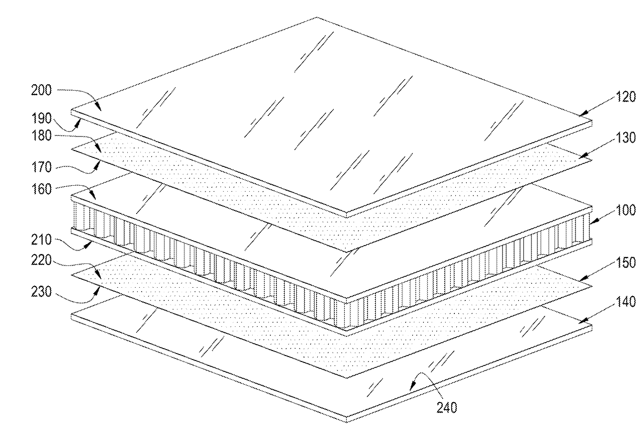
[0030]The invention addresses problems with the aforementioned techniques for bonding dissimilar materials that will be subjected to large temperature and / or pressure variations, including but not limited to those encountered in the space environment. In one embodiment, the method disclosed herein may create a thermally and mechani...


PUM

PropertyMeasurementUnit
temperatureaaaaaaaaaa
thicknessaaaaaaaaaa

Abstract

Disclosed herein is a method for bonding dissimilar materials using an elastic adhesive to permit the bond to withstand variations in temperature and pressure. The use of elastic adhesive accommodates previous problems associated with large differences in thermal expansion coefficient between dissimilar materials, and provides a thermally and chemically stable materials combination that withstands large thermal shock loads, such as may be experienced in a space environment. Also disclosed herein is a method for attaching a coating to a structure. In particular applications, the coating may be (1) specular (greater than 98% specularity); or (2) RF reflective for use in applications including but not limited to high frequency satellite communications.

Description

[0001]The invention described herein was made by employees of the United States Government, and may be manufactured and used by or for the United States Government for governmental purposes without payment of any royalties thereon or therefor.FIELD OF INVENTION[0002]This invention relates generally to a method of bonding dissimilar materials and more particularly to a method for bonding dissimilar materials to withstand wide thermal variations and / or a low ambient pressure environment, such as that found in space. The invention further relates to a method for applying a coating, which may be specular or RF reflective or a plurality of solar cells, to a structure with dissimilar material properties.BACKGROUND OF THE INVENTION[0003]Generally, there is a need for methods to bond dissimilar materials. There is a great need for such methods in applications where the bonded dissimilar materials will be subjected to thermal or pressure variations, low pressure / vacuum, or other stresses tha...

Claims


Application Information

Patent Timeline
Patent Type & Authority Applications(United States)
IPC IPC(8): B32B38/08B05D3/10C09J163/00B29C65/70B31B1/62B32B37/12B31B50/62
CPCB32B37/12Y10T156/10B32B2311/00C08G59/4207C08L63/00H01Q1/288H01Q15/144B29L2031/3456B29L2031/34B29L2031/3097B29C65/5057B29C66/1122B29D24/005B29C66/45B29C66/721B29C66/7254B29C66/73112B29C66/73751B29C66/73755C09J5/00F16B11/006C09J2400/163C09J2479/086B29C65/5021Y02E10/50H01L31/048B29C65/4825B29C65/483B29C65/4855H02S20/00B32B37/144
Inventor SEGAL, KENNETH N.LOHR, JAMES M.ROWLES, RUSSELLPETERS, WANDAKIWAK, ROBERT
Owner NASA
Why Eureka
Try Eureka