Power capture system and method

a technology of power capture system and power conversion system, which is applied in the direction of engine control, engine fuction, sea energy generation, etc., can solve the problems of increasing environmental risks, difficult installation, maintenance and control of power conversion system, and presenting technical difficulties in the extraction of wave power, so as to achieve low environmental impact, low environmental risk, and robust

Inactive Publication Date: 2012-08-02
AQUAMARINE POWER
View PDF4 Cites 8 Cited by
  • Summary
  • Abstract
  • Description
  • Claims
  • Application Information

AI Technical Summary

Benefits of technology

[0011]By providing for the control of the rate of flow of fluid from the fluid transfer conduit, the controller is able to assist in controlling the turbine apparatus to operate in an efficient range, despite surges in pressure associated with the wave motion.
[0064]The method may comprise controlling operation of the variable opening valve in dependence on a predetermined time constant, representative of a target time for reducing the difference between the actual pressure and the target pressure or between the actual flow rate and the target flow rate.

Problems solved by technology

However, the extraction of energy from wave power presents technical difficulties due in particular to the oscillating nature of the waves and to the significant variations in prevailing wave conditions over time.
However, such known wave power capture systems have generally included power conversion systems that are located sub-sea, at or near the mechanical devices, which makes installation, maintenance and control of the power conversion systems difficult.
In many cases, oil hydraulics are used in the power conversion systems, which provide additional environmental risks, for example in the event of sub-sea leakage.
Furthermore currently available examples of such oil hydraulic systems have relatively low maximum power limits and are not easily scaleable to higher powers.
In addition, the devices have tended to produce power unevenly with large ‘spikes’ in the output, making it difficult to provide a smooth power output suitable for delivery into an electrical grid system.
That means that the torque experienced by the motor can vary greatly over each wave cycle, which in turn can make efficient extraction of electrical power difficult.
Additionally the pulsating flow along the pipe results in surge (water hammer) which increases the difficulty of controlling the system.

Method used


Image

  • Power capture system and method
  • Power capture system and method
  • Power capture system and method

Examples


Embodiment Construction

[0089]Embodiments of the invention are now described, by way of non-limiting example, and are illustrated in the following figures:

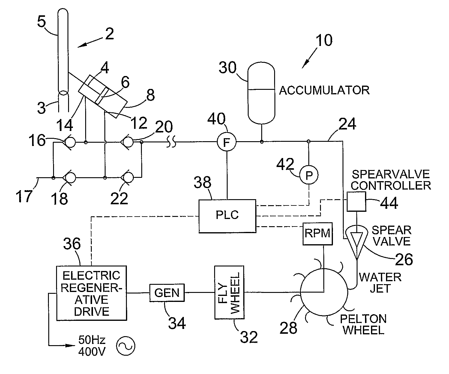
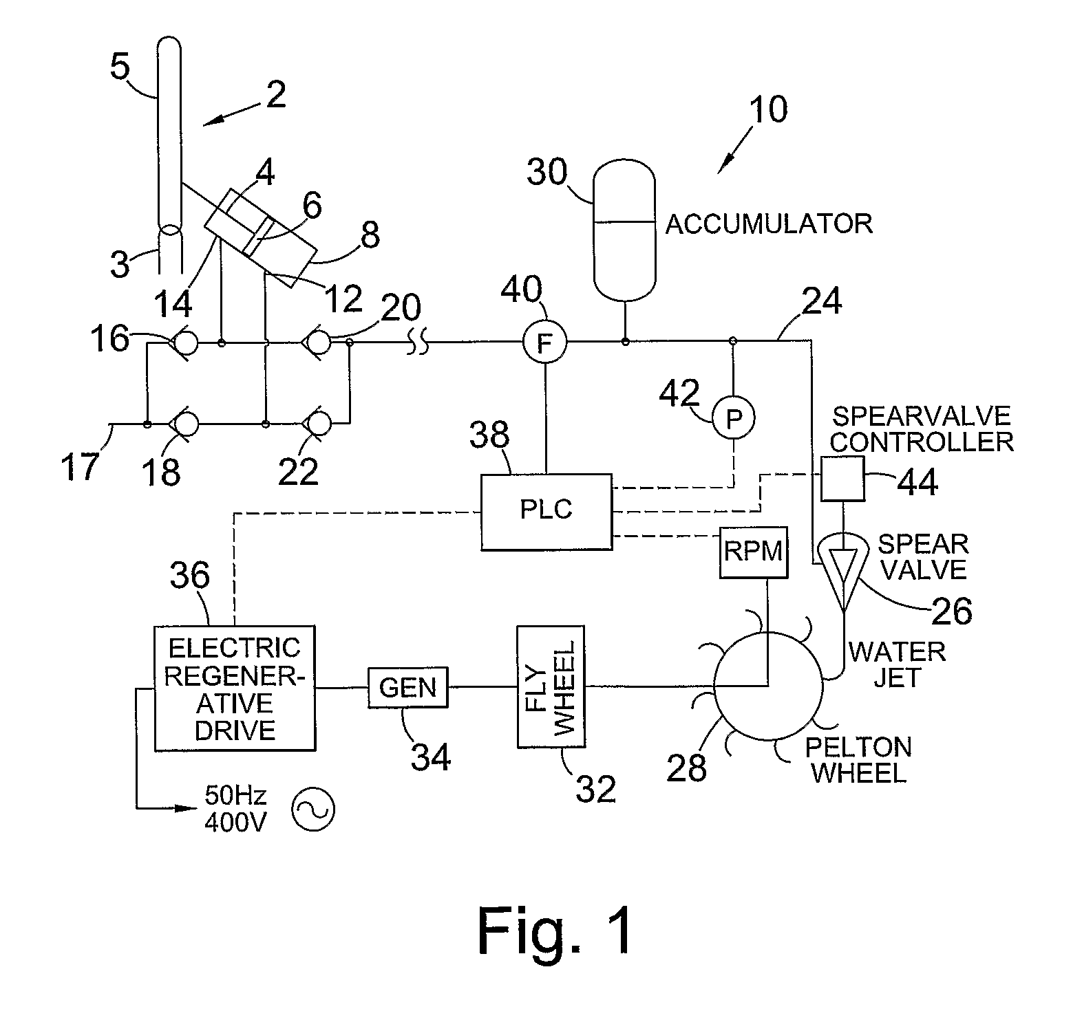
[0090]FIG. 1 is a schematic diagram of a wave power capture system;

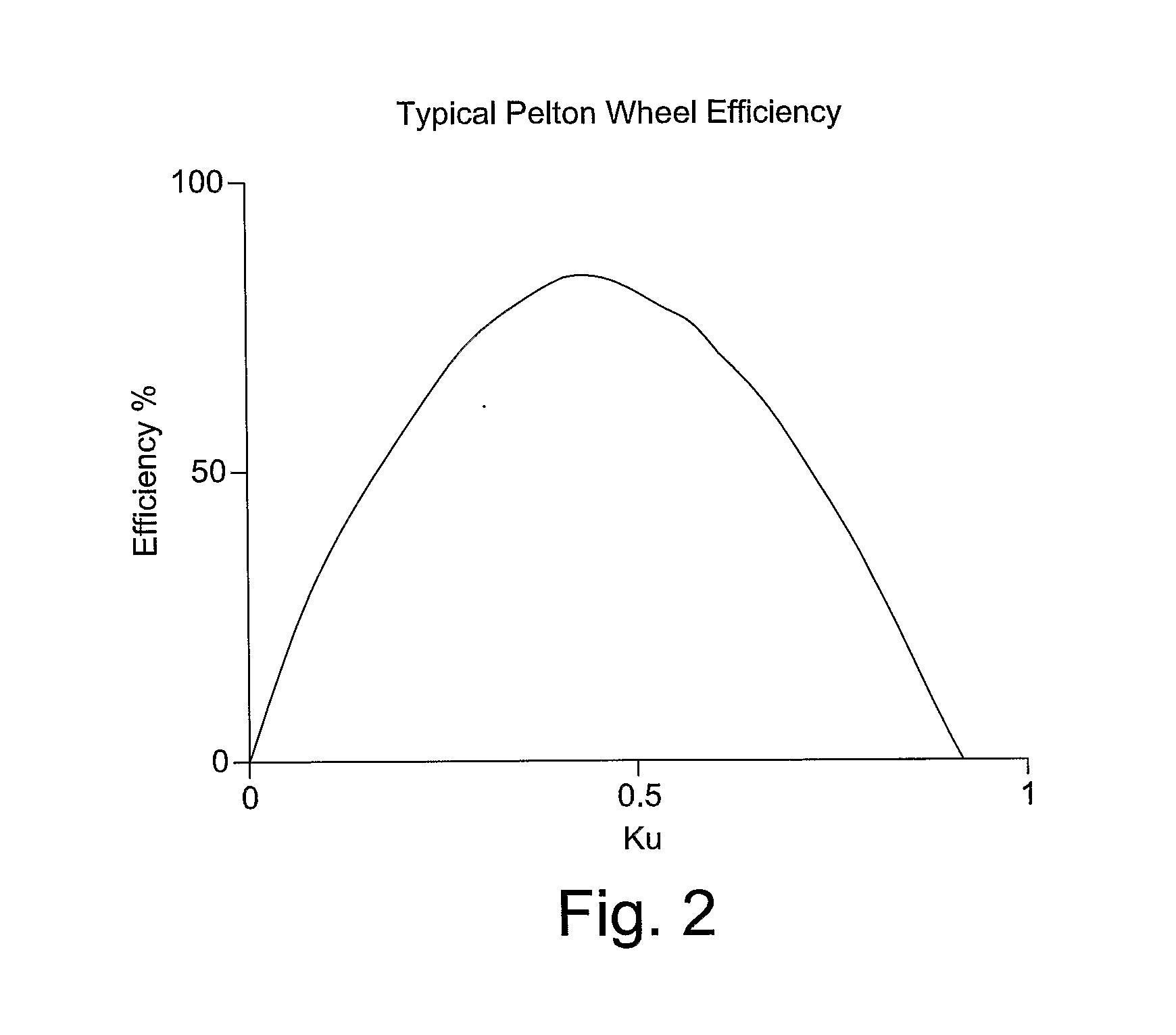
[0091]FIG. 2 is a graph of efficiency versus parameter Ku for a Pelton wheel;

[0092]FIG. 3 is flow chart illustrating in overview the control of operating speed and pressure in a short term control procedure, and the adjustment of an ideal pressure parameter in a long term control procedure, for the controller of the wave power capture system;

[0093]FIG. 4 is a more detailed flow chart illustrating a control procedure for the controller of the wave power capture system of FIG. 1;

[0094]FIG. 5 is a flow chart illustrating a self-optimisation process for tuning the system to the prevailing wave climate; and

[0095]FIG. 6 is a flow chart illustrating a start-up procedure and safety procedures for a mode of operation of the wave power capture system of FIG. 1.

[0096]FIG. 1 is a schematic illustrati...


PUM


Abstract

A wave power capture system, comprises a fluid transfer conduit for connection to a wave energy conversion device such that, in operation, the wave energy conversion device pressurizes fluid in the fluid transfer conduit in response to wave motion; a turbine apparatus arranged to receive fluid from the fluid transfer conduit; at least one sensor for sensing pressure and / or flow rate of the fluid; a variable opening valve for controlling the rate of flow of fluid from the fluid transfer conduit to the turbine apparatus; a controller for controlling operation of the variable opening valve in dependence upon the pressure and / or flow rate of the fluid sensed by the sensor and / or the speed of rotation of the turbine apparatus; and an electrical power generation system for obtaining electrical power from operation of the turbine apparatus.

Description

FIELD OF THE INVENTION[0001]The present invention relates to a power capture system and method, and in particular to a power capture system and method for obtaining electrical power from wave energy.BACKGROUND TO THE INVENTION[0002]Concerns about global warming and environmental pollution caused by the use of fossil fuels in energy generation has resulted in a move towards so-called ‘green’ energy sources, or renewable energy sources such as tidal movement, wave power and wind power.[0003]Hydroelectric power systems, in which the flow from a head of water, for example a reservoir, drives operation of turbines to produce electrical power are well known. Such hydroelectric power systems are relatively easy to control and the pressure and flow rate of the water are stable. Operating conditions of the turbines and associated generators can be tuned relatively easily to the prevailing conditions to provide maximum efficiency and electrical power output.[0004]It has long been recognised t...

Claims


Application Information

Patent Timeline
Patent Type & Authority Applications(United States)
IPC IPC(8): F03B13/14H02P9/04
CPCF03B1/02F03B13/182F03B15/20Y02E10/38F05B2270/1032F05B2270/1033Y02E10/223F05B2260/406Y02E10/20Y02E10/30F03B13/16
Inventor CROWLEY, MICHAEL DAVID
Owner AQUAMARINE POWER
Why Eureka
Try Eureka