
Sensor arrangements for measuring magnetic susceptibility

a technology of magnetic susceptibility and sensor, which is applied in the direction of susceptibility measurement, electrochemical generator, instruments, etc., can solve the problems of affecting cell capacity, affecting the ability of cells, and the method of determining the state of charge by subtracting the amount of charge used from the amount of charge initially placed in the cell, so as to accurately measure the very low level of magnetic field strength

Inactive Publication Date: 2012-08-02
METHODE ELETRONICS INC
View PDF7 Cites 22 Cited by
  • Summary
  • Abstract
  • Description
  • Claims
  • Application Information

AI Technical Summary

Benefits of technology

[0024]It is yet another object of the present invention to provide a sensor that can be easily mounted to the battery cell without adding substantial weight or requiring substantial change to the size of the battery cell.
[0025]It is yet another object of the present invention to provide a sensor housing attached to the mounting device for housing the sensor components to protect them from the surrounding environment.
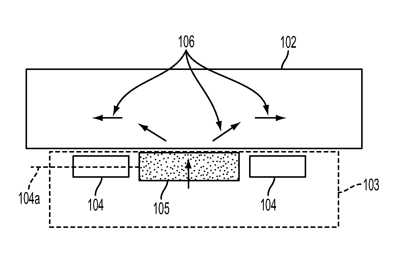
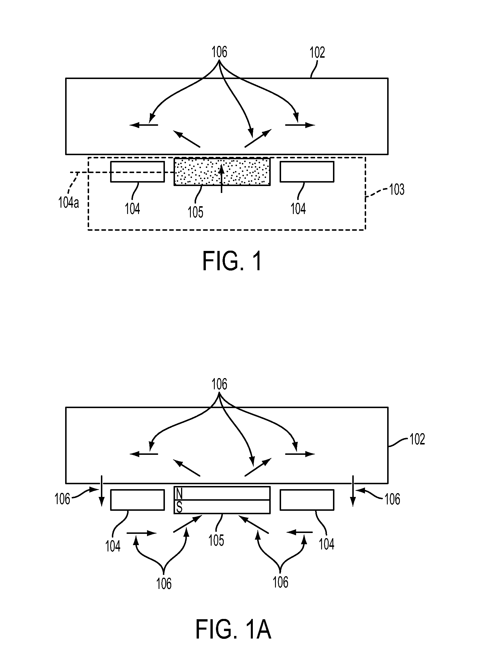
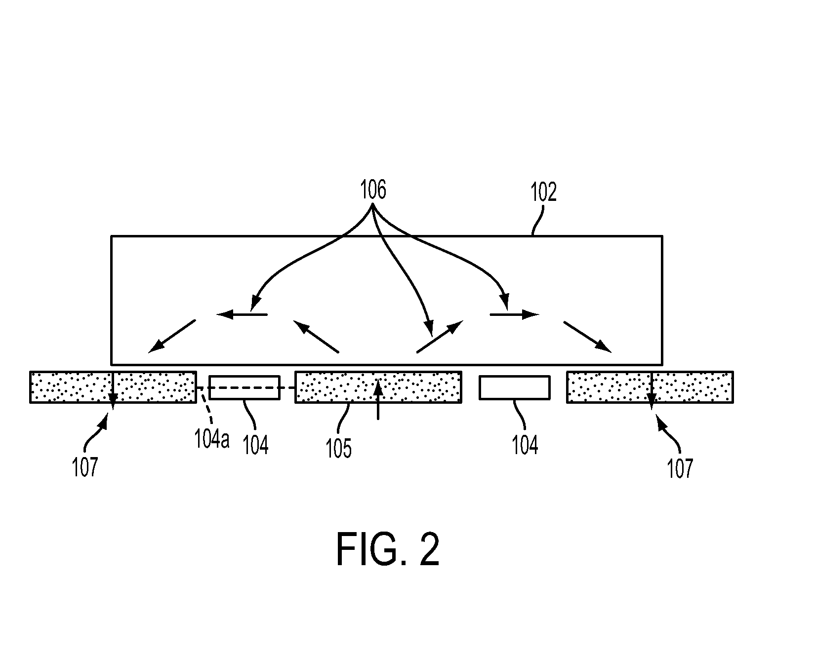
[0031]Those and other objects and advantages of the present invention are accomplished, as fully described herein, by a method comprising the steps of: using at least one permanent magnet to generating a magnetic field; directing the magnetic field through a battery cell electrolyte and / or electrode; and using one or more fluxgate coils to measuring the resulting magnetic field strength after the magnetic field has been linked through the electrolyte and or electrodes. Fluxgate coils are used in the preferred embodiment due to their ability to accurately measure very low levels of magnetic field strength, and the at least one permanent magnet is positioned such that its principal flux path through the battery cell is in a direction substantially normal to the sensitivity axis of the at least two sense coils.

Problems solved by technology

However, because the charge is stored chemically, each charge-discharge cycle (as well as normal temperature cycling, vibration, shock, etc.) results in irreversible changes within the individual cells, the changes affecting cell capacity.
Thus, the aforementioned method of determining the state of charge by subtracting the amount of charge used from the amount of charge initially placed in the cell is flawed, because the actual charge capacity of the cell is reduced over time and usage at an unknown rate.
The risk resulting from uncertainty with respect to a battery's state of charge is that an inconvenience will result if the battery charge falls below useful levels.
However, regardless of the technology used, it is still necessary to actively monitor the battery's state of charge.
In purely electric vehicles, this need rises beyond convenience because, in such vehicles, there is no motive backup as is the case with hybrid vehicle configurations.
Such a method is prone to numerous errors.
Because a battery is comprised of numerous cells connected in series and / or parallel, an individual cell that is behaving as a statistical outlier in relation to the other cells, can significantly degrade the function of the battery as a whole.
There are a number of limitations to this approach.
Any resistive or reactive influence to the circuit will add error to the measurement.
In addition to the obvious packaging issues, larger coils require substantially more power for excitation at the requisite levels, leading to less efficiency and increased likelihood of propagating electromagnetic fields that may interact with other measurement coils or nearby electronics.
Packaging, location, and other design limitations of the system may result in minimal difference in field strength between the primary and secondary magnetic fields.
In practice, the difference between the primary and secondary fields may so small, that measurement of that difference lacks usefulness due to limitations of the magnetic field sensor resolution and / or accuracy.
However, design limitations may place restrictions on the size, location, and orientation of the flux directors, and the highly permeable materials used in their construction are expensive and subject to wide variations and cost due to limited supply.
Adding further uncertainty to the state of charge measurement is the potential variation in the primary magnetic field strength, which, even if the primary field is modulated so as to distinguish from ambient magnetic fields, will nonetheless corrupt the output of the secondary magnetic field sensor which is tuned to the same modulation parameters.
However, those methods are costly and may be unsuitable for practical applications.
Furthermore, those methods may not work with all types of electrolytes, especially those that are less mobile, which is the case for lithium-ion batteries.

Method used


Image

  • Sensor arrangements for measuring magnetic susceptibility
  • Sensor arrangements for measuring magnetic susceptibility
  • Sensor arrangements for measuring magnetic susceptibility

Examples


Embodiment Construction

[0040]Several preferred embodiments of the invention are described for illustrative purposes, it being understood that the invention may be embodied in other forms not specifically shown in the drawings. The figures are described with respect to the system architecture and methods for using the system to achieve one or more of the objects of the invention and / or receive the benefits derived from the advantages of the invention as set forth above.

[0041]The present invention is directed to a sensor for measuring the magnetic susceptibility of an object by generating a magnetic field that permeates the object and by sensing the resultant changes in that magnetic field. The “object” of which the magnetic susceptibility is to be measured may be a volume with constant or variable magnetic susceptibility, as may be related to some other physical quantity or condition. Examples of the physical condition include but are not limited to the material temperature, the concentration of ions in th...


PUM

PropertyMeasurementUnit
state of chargeaaaaaaaaaa
magnetic fieldaaaaaaaaaa
magnetizationaaaaaaaaaa

Abstract

A device and method for determining the state of charge of an object, such as an electrochemical battery cell. The device includes a state of charge sensor having a primary magnet that creates a primary magnetic field, and at least one magnetic field sensing element. The sensitivity axes of the sensing elements are substantially perpendicular to the direction of polarization of the primary magnet. The primary magnet and the sensing elements are placed in the proximity of the object, and magnetic fields resulting from the magnetic susceptibility of the object are measured by the sensing elements. The sensing elements output an electrical signal from which the state of charge of the object can be determined.

Description

CROSS REFERENCE TO RELATED APPLICATION[0001]The present application is related to and claims the benefit of U.S. Provisional Patent Application No. 61 / 427,994, filed Dec. 29, 2010, whose disclosure is hereby incorporated by reference in its entirety into the present disclosure.BACKGROUND OF THE INVENTION[0002]1. Field of the Invention[0003]The present invention relates to devices and methods for measuring the magnetic susceptibility of an object. In particular, the present invention is related to a device and method for measuring the magnetic susceptibility of a battery cell, in which the magnetic susceptibility provides an indication of the state of charge of the battery cell. The present invention exhibits an improved signal-to-noise ratio when measuring the magnetic susceptibility of the battery cell.[0004]2. Description of the Related Art[0005]A battery includes one or more cells, connected in a series and / or parallel arrangement, that chemically store electrical charge potentia...

Claims


Application Information

Patent Timeline
Patent Type & Authority Applications(United States)
IPC IPC(8): G01N27/416G01N27/76
CPCG01R31/3606H01M10/48G01R33/16G01R31/382Y02E60/10
Inventor MORAN, TIMOTHY
Owner METHODE ELETRONICS INC
Learn More