

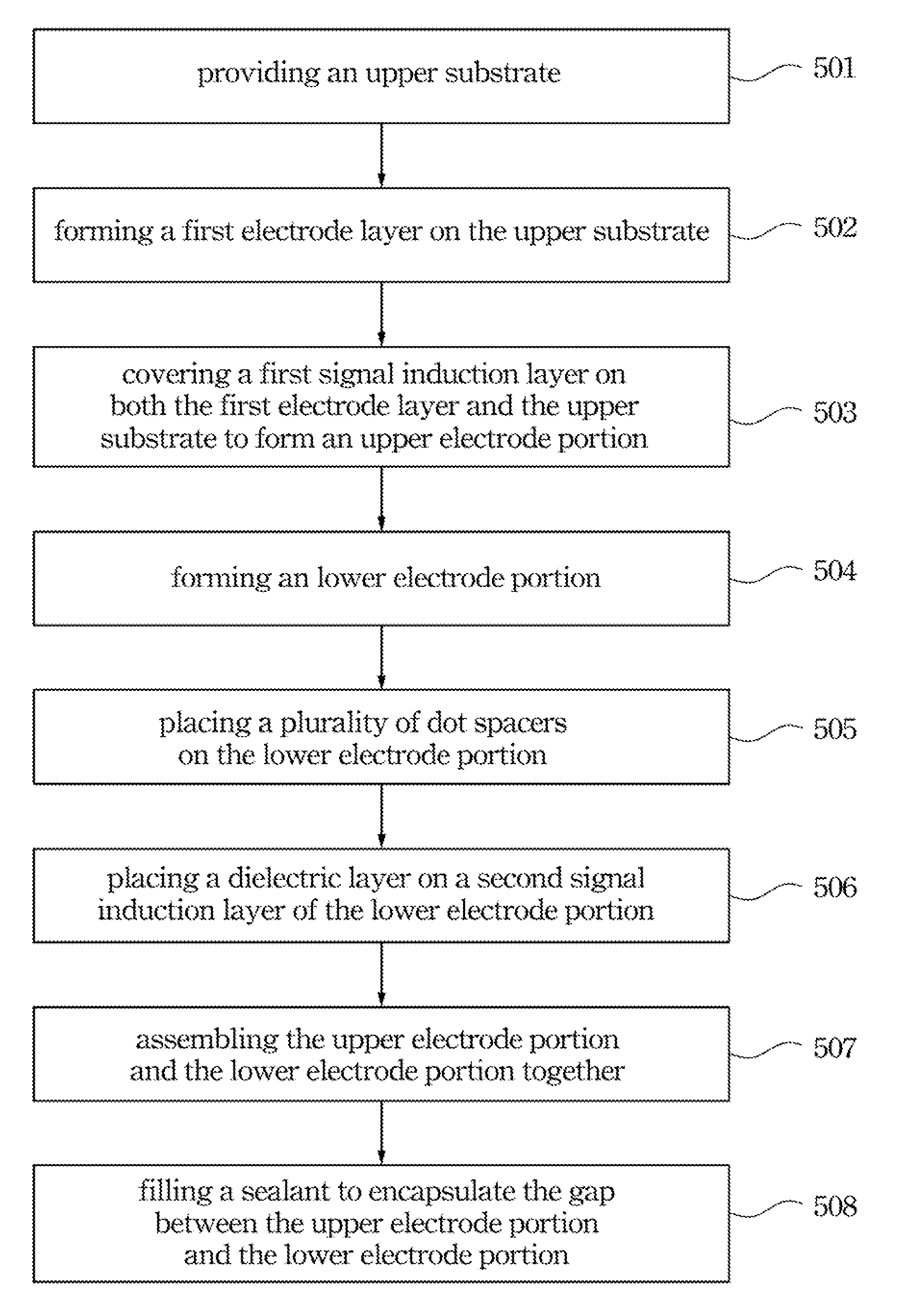
Touch panel and method of manufacturing the same
a technology of touch panel and manufacturing method, which is applied in the field of touch panel, can solve the problems of reducing the product life, inconvenience and disadvantages of conventional touch panel mentioned above, and so as to prolong the product life of the touch panel and reduce the damage. , the effect of reducing the vertical distance between the first signal induction layer and the second signal induction layer
- Summary
- Abstract
- Description
- Claims
- Application Information
AI Technical Summary
Benefits of technology
Problems solved by technology
Method used
Image


Examples
Embodiment Construction
[0034]In the following detailed description, for purposes of explanation, numerous specific details are set forth in order to provide a thorough understanding of the disclosed embodiments. It will be apparent, however, that one or more embodiments may be practiced without these specific details. In other instances, well-known structures and devices are schematically shown in order to simplify the drawings.
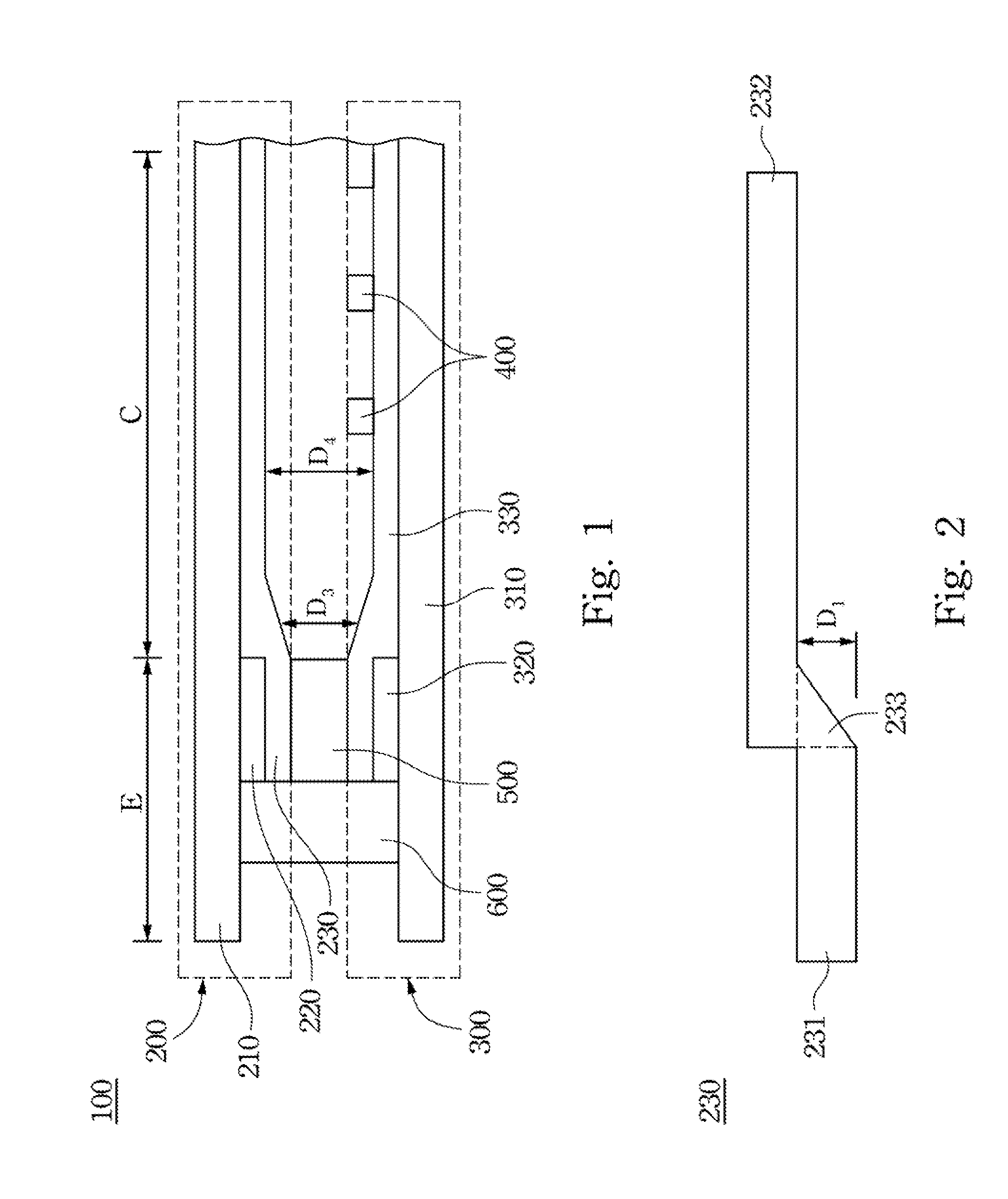
[0035]In view of the position of the conventional transparent conductive film neighboring to the peripheral region thereof may easily get elastically fatigued, even to cause cracked after being pressed for many times, so that the product life of the conventional transparent conductive film of the touch panel will be reduced quickly so as to lead malfunction of the entire product in use. Therefore, the present invention is to disclose a touch panel for intensifying the structural strength of the transparent conductive film neighboring to the peripheral region, so as to amplify the p...
PUM
 Abstract
Description
Claims
Application Information