Adaptive light emitting diode dimming driving circuit

a technology of light-emitting diodes and driving circuits, which is applied in the direction of electroluminescent light sources, electric lighting sources, and use of semiconductors. it can solve the problems of inaccurate dimming effect, affecting the efficiency of the whole circuit, and serious damage to energy conversion efficiency, so as to prevent led from twinking, increase work efficiency, and reduce costs

Inactive Publication Date: 2014-06-26
UNITY OPTO TECH CO LTD
View PDF0 Cites 10 Cited by
  • Summary
  • Abstract
  • Description
  • Claims
  • Application Information

AI Technical Summary

Benefits of technology

[0008]Therefore, upon the foregoing defects in prior arts, it is a primary objective of the present invention to provide an adaptive LED dimming driving circuit to control the magnitude of outputted driving voltage energy by means of linear regulation, thus preventing the LED from twinkling and retaining TRIAC dimming feature.
[0009]According to an objective of the invention, the adaptive LED dimming driving circuit is installed to a lamp board to drive and linearly regulate the illumination brightness of at least an LED and disposed with a dimming module, a rectification module and a control module. The rectification module is electrically connected to an external power source through the dimming module. The control module is electrically connected to the rectification module and the LED. The control module has a control chip, a regulator and a sensing resistor. The LED is coupled to the control chip through the regulator and the sensing resistor that are cascaded so that a sensing value is formed and fed back to the control chip after the sensing resistor senses a driving current ILED flowing through the LED. The sensing value is compared with a reference value to control the regulator regulating the driving current ILED. The feature of the adaptive LED dimming driving circuit is that the rectification module is coupled to the dimming module through a regulator capacitor connected in parallel. The control module is disposed with a first resistor, a second resistor, a retainer, a third resistor and a fourth resistor. The retainer is electrically connected to the rectification module, the first resistor, the second resistor and the control chip. The first resistor is coupled to the second resistor and the control chip. The third resistor is electrically connected to the rectification module and the control chip. One end of the fourth resistor is coupled to the LED and the control chip while another end of the fourth resistor is coupled to the regulator and the sensing resistor, wherein when the rectification module outputs an input voltage to form an input current Iin, the control chip drives the retainer to outputs a retaining current hhold to the second resistor so that the input voltage is consumed by the second resistor to retain a normal work of the dimming module. The first resistor divides the input voltage to allow the control chip to detect a dimming intensity of the dimming module real-time such that under a condition of allowing the input current satisfying a correlation Iin=Ihold+ILED, the retaining current has a minimum current value to increase a work efficiency when the LED is regulated to a maximum brightness; wherein when the input voltage raises, an across voltage at two ends of the fourth resistor is increased to compensate an across voltage at two ends of the sensing resistor so that the driving current ILED is reduced to achieve a constant power state, and the third resistor divides voltages and detects a ripple value of the input voltage. When the input voltage is reduced and the ripple value is smaller than a standard value, the control chip reduces the reference value to prevent the LED from generating twinkling phenomenon.
[0010]The circuit architecture of the invention does not utilize transformers or inductors to switch PWM signals so that there is no EMI problem, and there is no need to dispose safety components. Therefore, costs can be reduced, and the input voltage energy can be properly detected to regulate the magnitude of TRIAC retaining current so that problems of power consumption and much heat energy can be avoided due to outputted retaining current when the LED is regulated to the maximum brightness such that effects of improving the whole circuit efficiency to retain above 0.9 high power factor, stable illumination quality and improved product service life can be achieved. Moreover, the ripple value of the input voltage is detected by the third resistor. Therefore, when the brightness of the LED is reduced to decrease the input current, the control chip is properly reduced to determine whether or not the reference voltage level of the regulator is driven, thereby preventing the LED from generating twinkling phenomenon.

Problems solved by technology

Consequently, the energy conversion efficiency will be seriously damaged.
Accordingly, the foregoing dimming method may affect the whole circuit efficiency due to different changes of voltages and current, and the problem of inaccurately dimming effect may occur.
Moreover, the circuit architecture utilizing the transformer or the inductor to realize the switching of duty ratio of PWM signals has problems of electromagnetic interference (EMI) and twinkling.
At this time, if safety components are increased, the work efficiency of the whole circuit is reduced to cause non-practicality.
It may still work due to retaining current to form high idle work consumption since the LED is regulated to reach the maximum light emitting brightness.

Method used


Image

  • Adaptive light emitting diode dimming driving circuit
  • Adaptive light emitting diode dimming driving circuit
  • Adaptive light emitting diode dimming driving circuit

Examples


Embodiment Construction

[0017]The technical content of the present invention will become apparent by the detailed description of the following embodiments and the illustration of related drawings as follows.

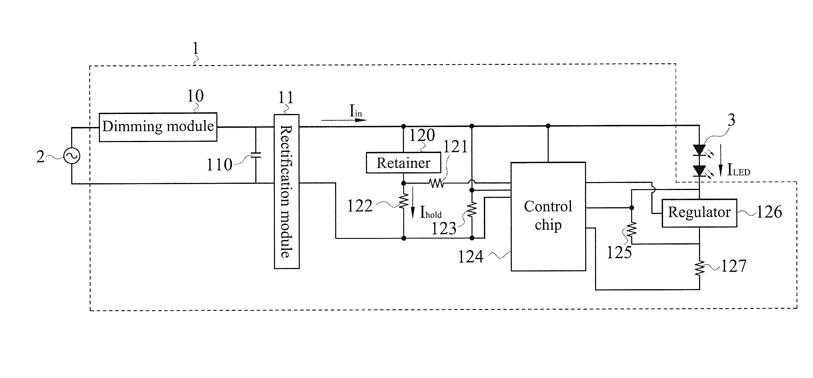
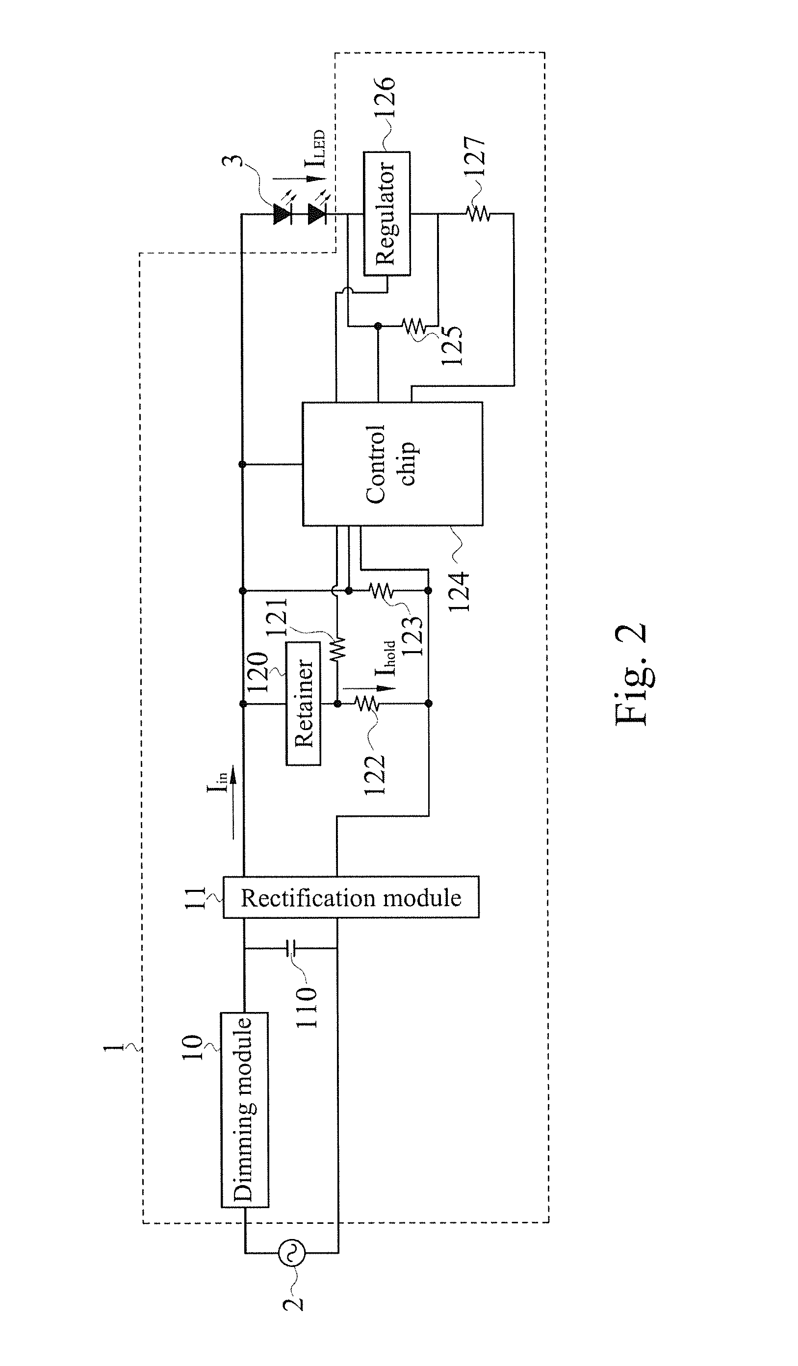
[0018]With reference to FIG. 2 to FIG. 4 for a block diagram of an implementation and a block diagram and a circuit diagram of a second implementation according to a preferred embodiment of the invention are depicted. As shown in the figures, the adaptive LED dimming driving circuit 1 is normally disposed to a lamp board of a lamp to convert voltage energy of an external power source 2 so as to drive and linearly regulate the illumination brightness of at least an LED 3. The adaptive LED dimming driving circuit 1 is disposed with a dimming module 10, a rectification module 11 and a control module 12. The dimming module 10 is a TRIAC linear dimming circuit. The rectification module 11 is a bridge full-wave rectifier circuit coupled to the external power source 2 through the dimming module 10 after two en...


PUM


Abstract

An adaptive LED dimming driving circuit is disclosed, wherein its control module is disposed with a first resistor, a second resistor, a retainer, a third resistor and a fourth resistor. When the control module receives an input voltage, the retainer is driven to output a retaining current Ihold to the second resistor, thereby ensuring normal dimming. The first resistor and the third resistor detect the input voltage so that when an input current Iin satisfies a correlation Iin=Ihold+ILED, the retaining current has the minimum value to increase work efficiency during the LED that is dimmed to the maximum intensity. When the input voltage is too low, the reference level is reduced to prevent the LED from generating twinkling. The fourth resistor detects the voltage energy of the LED. Therefore, when the voltage energy is changed, a high-low-voltage compensation is performed to achieve a constant power state.

Description

CROSS-REFERENCE TO RELATED APPLICATIONS[0001]This non-provisional application claims priority under 35 U.S.C. §119(a) on Patent Application No(s). 101149726 filed in Taiwan, R.O.C. on Dec. 25, 2012, the entire contents of which are hereby incorporated by reference.BACKGROUND OF THE INVENTION[0002]1. Field of the Invention[0003]The invention relates to a technical field of light emitting diode (LED) power equipment, and more particularly to an adaptive LED dimming driving circuit supporting TRI-electrode AC switch (TRIAC) that flexibly compensates outputted driving electricity by means of detecting the inputted electricity ripple voltage difference real-time so that the work efficiency of whole circuit can be improved, and the twinkling problem on LEDs can also be prevented.[0004]2. Description of the Related Art[0005]Currently, the driving circuit of an LED lamp is to linearly regulate the LED brightness and is accomplished by means of switching an input voltage conduction angle thr...

Claims


Application Information

Patent Timeline
Patent Type & Authority Applications(United States)
IPC IPC(8): H05B33/08H05B44/00
CPCH05B33/0836H05B33/0815H05B45/37H05B45/395Y02B20/30
Inventor WU, CHIH-HSIENCHANG, WEILU, HUAN-YINGCHUANG, KAI-CHENGCHIU, SHAO-WEI
Owner UNITY OPTO TECH CO LTD
Why Eureka
Try Eureka