
Device and method for processing printing substrate web into printed products

a technology of printing substrate and printing product, which is applied in the direction of rotary presses, optics, instruments, etc., can solve the problems of synchronizing print units, increasing cutting or trimming expenditure, and increasing waste, so as to reduce production costs and expand the flexibility of the device

Inactive Publication Date: 2012-08-02
MULLER MARTINI HLDG
View PDF2 Cites 16 Cited by
  • Summary
  • Abstract
  • Description
  • Claims
  • Application Information

AI Technical Summary

Benefits of technology

[0009]It is therefore an object of the invention to provide a method and a device for processing a printing web which method and device permit early in the process to configure the synchronizing of the printing web with the a further processing operations, in order to be more cost-effective and flexible.
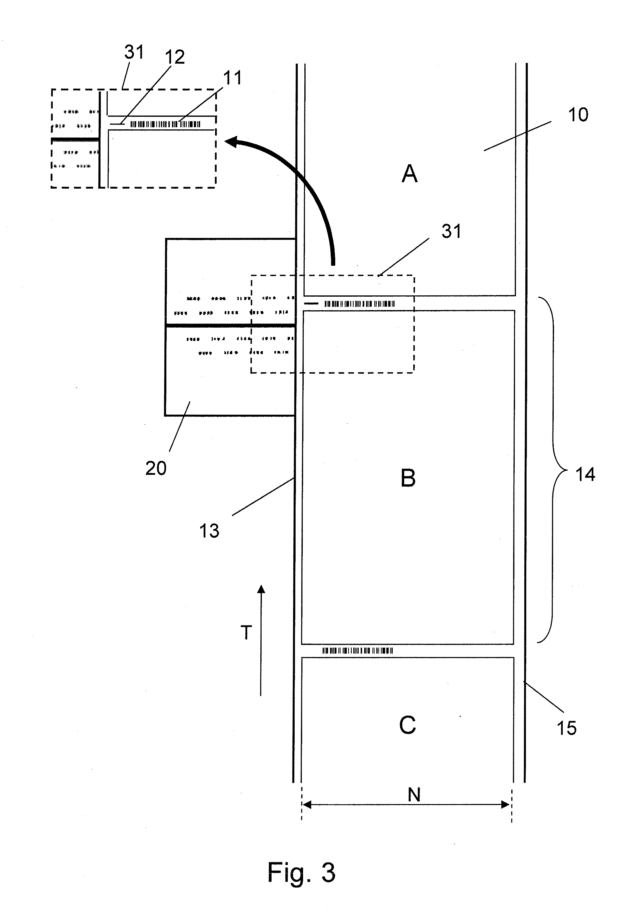
[0013]One advantage of the method and the device according to the invention is that an unprinted strip in the transporting direction of the web is not required since the print marks can be printed onto the useful strip of the web. As a result of using coded print marks, it is furthermore possible to identify a web region that is currently located in a further processing device. On the one hand, these advantages lead to a savings of printing web which reduces the production costs while, on the other hand, they also result in a more flexible processing since the coding of the print marks makes it possible to determine position information for the web and / or the sheets printed onto the web. The subsequent processing steps can thus be adapted easier to the momentary requirements of the further processing device. The flexibility is important, in particular for the digital printing, because constantly changing formats of the printing web must be processed and the editions can become small enough to comprise only one copy.
[0014]It is preferable if a stationary reference element, which comprises machine-readable markings, is provided for the device according to the invention. The reference element expands the flexibility of the device according to the invention by helping generate correction values for synchronizing the web with the following processing operation, as described in further detail below.

Problems solved by technology

However, leaving an unprinted strip on the web for affixing the print marks results in additional cutting or trimming expenditure and produces more waste.
The problem of synchronizing print units basically is the same as the problem of synchronizing the downstream-arranged further processing devices, up to the cross cutter for the printed web.
The disadvantage of these methods is that they can be used only if the print marks are in a clear space, meaning no other print exists in the area immediately surrounding the marks, at least not in movement direction of the printed web.
Light scanners such as matrix cameras which read in the print marks generally used nowadays cannot reliably distinguish between the print marks and the remaining print.
However, the unprinted region between two sheets must be large enough, so that the variation in the transport distance is smaller than the unprinted region containing the print marks, wherein this generally again results in a lot of cutting and trimming and thus a costly paper loss.
However, these methods are expensive and furthermore difficult to realize in the downstream processing regions, in particular with the digital printing where the content printed onto the sheets changes constantly.
However, the code printing location does not directly relate to the code function, meaning that if a code is printed with an offset of only a few millimeters it cannot be used by the further processing devices which read and interpret the code.

Method used


Image

  • Device and method for processing printing substrate web into printed products
  • Device and method for processing printing substrate web into printed products
  • Device and method for processing printing substrate web into printed products

Examples


Embodiment Construction

[0021]In the Figures, the same reference numbers denote components which operate the same way or have the same effect.

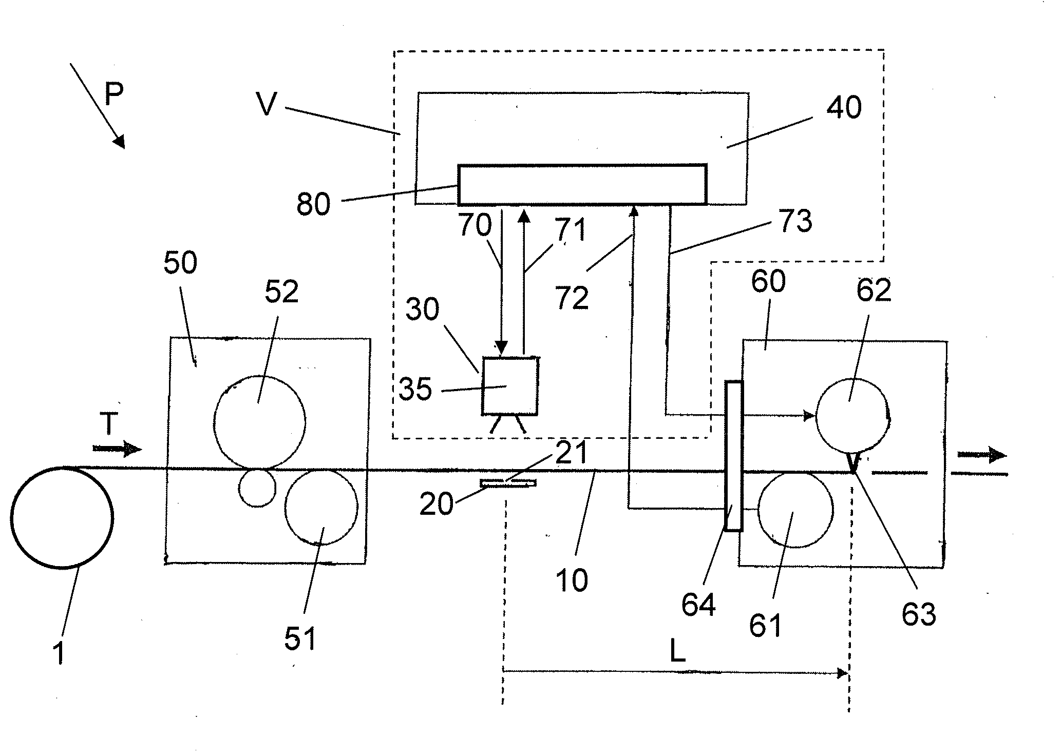
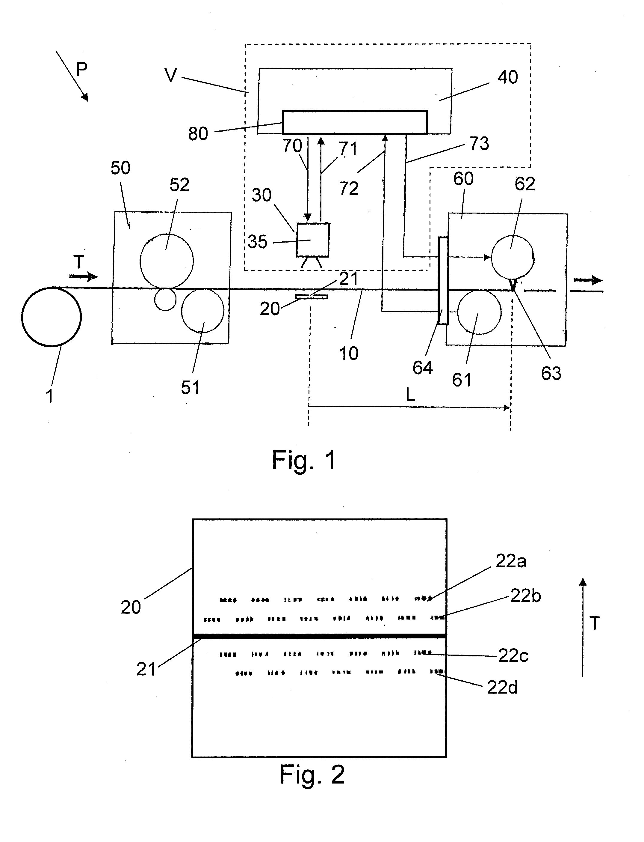
[0022]FIG. 1 shows a view from the side of a simplified further processing system P in which an exemplary embodiment of the device V is used. A web 10 comprising a printing substrate is unwound from a reel 1 and is supplied to a printing press 50. The printing press 50 comprises a print unit 52 and a drive 51, for example a first servo unit, for transporting the web 10 in a direction T. The drive 51 essentially determines the speed of the printing substrate which consists of paper for the embodiment described herein. Of course, other printing substrates such as foils, for example, can also be used for web 10.

[0023]The printed web 10 which arrives from the printing press 50 is cut into individual printed sheets in a further processing device 60, embodied as a cross cutter. This cross cutter is used only as an example for a further processing device 60, wherein this ca...


PUM


Abstract

A method for processing a web to form printed products includes affixing a print mark assigned to a printed sheet of the web to a useful strip of the web. The print mark includes a coded print mark. An image is recorded that shows a region of the web in which the affixed print mark is located. The print mark in recorded image is searched for and identified. A position of the print mark in the recorded image is determined, and based on the determined position, the position of the print mark on the web is inferred. A correction value is determined for synchronizing a subsequent further processing of the web in dependence on the position of the print mark on the web.

Description

CROSS-REFERENCE TO RELATED APPLICATION[0001]This application claims the priority of the Swiss Patent Application No. 00157 / 11, filed on Jan. 28, 2011, the subject matter of which is incorporated herein by reference.BACKGROUND OF THE INVENTION[0002]The invention relates to a method for processing a web composed of a printing substrate to form printed products, as well as to a device for realizing the method.[0003]When using rotary or web-fed printing presses operating with an offset or gravure printing process, as well as high-capacity digital printing presses, the printing operation starts when the web leaves the reel. Following the printing operation, the web must then be cut into sections and, if applicable, folded into signatures. The web generally travels a longer distance between the location of printing and the processing devices used for cutting and folding the printed sheets or signatures. In the process, the print image must be aligned so as to be synchronized with the cros...

Claims


Application Information

Patent Timeline
Patent Type & Authority Applications(United States)
IPC IPC(8): G03B27/42
CPCB41F13/025B41F13/60B41F33/0081B26D5/34B26D1/405B26D5/007B41P2233/52
Inventor DUSS, HANSPETERGYSIN, CHRISTOPHBRACHER, MARKUS
Owner MULLER MARTINI HLDG
Learn More