Optical module and spectroscopic analyzer

Active Publication Date: 2012-08-02
PURDUE RES FOUND INC +1
View PDF5 Cites 11 Cited by
  • Summary
  • Abstract
  • Description
  • Claims
  • Application Information

AI Technical Summary

Benefits of technology

[0024]According to the above aspect, since the spectroscopic analyzer includes the optical module of the above aspect, it is possible to suppress a decrease in the resolution. Thus, the light receivi

Problems solved by technology

As above, when the reflecting film is deformed, there is a problem in that the transmission wa

Method used


Image

  • Optical module and spectroscopic analyzer
  • Optical module and spectroscopic analyzer
  • Optical module and spectroscopic analyzer

Examples


first embodiment

6. Operation and Effect of First Embodiment

[0100]According to the first embodiment described above, the following effects are obtained.

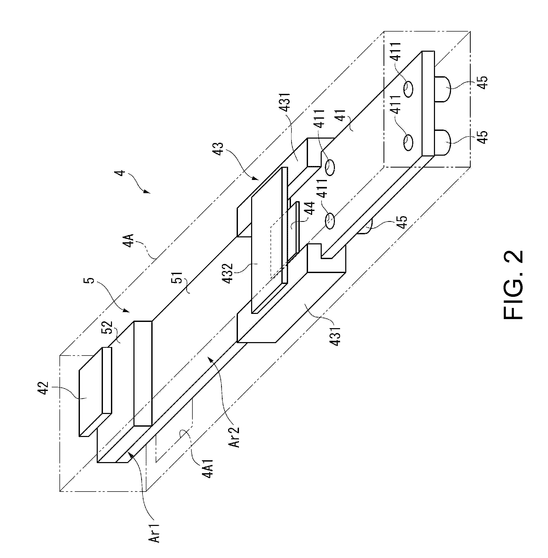
[0101]According to the present embodiment, the etalon 5 includes the light interference area Ar1 facing the first and second substrates 51 and 52 and the protruding area Ar2 protruding from the light interference area Ar1. Moreover, the holding member 43 holds the distal end side (a side opposite to the light interference area Ar1) of the protruding area Ar2 to thereby hold the etalon 5. Thus, since the etalon 5 is held by the holding member 43 at a position away from the light interference area Ar1 where the respective mirrors 54 and 55 are formed, no stress will be applied to the light interference area Ar1 due to the holding force of the holding member 43. Therefore, it is possible to prevent deformation of the substrates 51 and 52 and deformation of the mirrors 54 and 55.

[0102]Moreover, even when heat is transmitted from the light source device 2...

second embodiment

[0105]Next, an etalon 5A of a colorimetric device according to a second embodiment of the invention will be described with reference to the drawings.

[0106]FIG. 7 is a plan view of a first substrate 51A of the etalon 5A according to the second embodiment, and FIG. 8 is a plan view of an interposer 7 of the etalon 5A. In addition, since the second substrate 52 of the etalon 5A of the present embodiment has the same configuration as the first embodiment, the second substrate 52 will not be illustrated, and instead, will be described by appropriately referring to FIG. 5.

[0107]The etalon 5 of the first embodiment described above has a two-layer configuration which includes the rectangular parallelepiped first substrate 51 and the square second substrate 52, and in which the protruding area Ar2 is formed on the first substrate 51. In contrast, the etalon 5A of the second embodiment is different in that it has a three-layer configuration which includes square first and second substrates 51...

third embodiment

[0126]FIG. 9 is a plan view showing a first substrate 51B of an etalon 5B according to a third embodiment.

[0127]The etalon 5B of the third embodiment has substantially the same configuration as the first substrate 51 of the etalon 5 according to the first embodiment but is different in that a pair of cutout portions 8 (vibration absorbing portions) is formed in the protruding area Ar2 of the first substrate 51B.

[0128]In the following description, the same constituent elements as the first embodiment described above will be denoted by the same reference numerals, and the description thereof will not be provided.

[0129]The cutout portions 8 suppress vibration from being transmitted from the outside to the light interference area Ar1. The cutout portions 8 are formed in the protruding area Ar2 of the first substrate 51B by notching the side edges extending in the protruding direction of the protruding area Ar2 of the first substrate 51B in a concave U-shape in the plan view shown in FIG...


PUM


Abstract

A colorimetric sensor includes an etalon including a first substrate, a second substrate facing the first substrate, a fixed mirror formed on a surface of the first substrate facing the second substrate, and a movable mirror formed on the second substrate so as to face the fixed mirror with a prescribed gap therebetween, a light receiving element that receives a test subject light having passed through the etalon, and a holding member holding the etalon. The etalon includes a light interference area facing the first and second substrates in a plan view as seen in a thickness direction of the substrate, and a protruding area protruding from the light interference area. The holding member holds the etalon at one end side of the protruding area opposite to the light interference area.

Description

BACKGROUND[0001]1. Technical Field[0002]The present invention relates to an optical module including an interference filter that extracts light of a prescribed wavelength from an incident light and a spectroscopic analyzer including the optical module.[0003]2. Related Art[0004]In the related art, an interference filter (etalon) in which multi-layer films (reflecting films) are disposed on the facing surfaces of a pair of substrates so as to face each other with a prescribed gap therebetween is known (for example, see JP-A-11-142752).[0005]In the interference filter disclosed in JP-A-11-142752, driving electrodes are disposed on the facing surfaces of the pair of reflecting films so as to face each other in order to adjust the gap, and the gap can be adjusted by an electrostatic attractive force by applying a driving voltage to the respective driving electrodes. In this way, the interference filter can pass only light of a specific wavelength corresponding to the gap. That is, the in...

Claims


Application Information

Patent Timeline
IPC IPC(8): G01J3/45G02B27/00
CPCG01J3/26G02B26/001G01J3/50
Inventor NOZAWA, TAKESHI
Owner PURDUE RES FOUND INC
Why Eureka
Try Eureka