Laser marked device

a laser marking and laser technology, applied in the field of laser marking devices, can solve the problems of inability to be put into practice, inability to present synthetic images, and inability to contain micro-optic systems capable of laser marking micro-optic film materials, etc., to achieve the effect of enhancing the security features of these documents and increasing the complexity

Active Publication Date: 2012-08-02
VISUAL PHYSICS LLC (US) +2
View PDF1 Cites 53 Cited by
  • Summary
  • Abstract
  • Description
  • Claims
  • Application Information

AI Technical Summary

Benefits of technology

[0006]An object of the present invention is to increase the complexity and thus the counterfeit-resistance of these secure documents by incorporating laser markable or laser marked optical (e.g., micro-optic) film materials. The static 2D images laser marked on, within, or below these film materials help determine the authenticity of the documents (e.g., documents having financial value, identity documents, non-secure documents) and products that employ them. The inventive materials may also be used simply for brand enhancement purposes (e.g., as (or as part of) a product label) with the laser marked 2D image providing, for example, a company logo or other brand identifier.
[0007]Laser personalization is widely used as a means to add customized personalization data to secure documents at the point of issue. This personalization feature further protects a secure document being issued by a government or corporate entity by allowing the issuer to personalize the document with the intended recipient's personal information. By way of the present invention, this type of personalization feature has been incorporated onto, into, or below an optical film material suitable for use with secure documents thereby enhancing the security features of these documents. In the past, micro-optic systems capable of presenting synthetic images did not contain laser markable substrate materials. Also, to this point in time, laser markable products have not contained micro-optic systems capable of presenting synthetic images.

Problems solved by technology

Also, to this point in time, laser markable products have not contained micro-optic systems capable of presenting synthetic images.
Laser marking micro-optic film materials has in the past been deemed impracticable (i.e., not capable of being put into practice) due to the risk of causing permanent damage to these materials.
As is known to those skilled in the art, laser writing causes overheating and swelling of these film materials, which results in bubbling, separation, or delamination at interfaces within the structure, and / or permanent damage to the microlenses and / or micro-sized image icons, thus causing permanent distortion of the synthetic images.

Method used


Image

  • Laser marked device
  • Laser marked device
  • Laser marked device

Examples


example 1

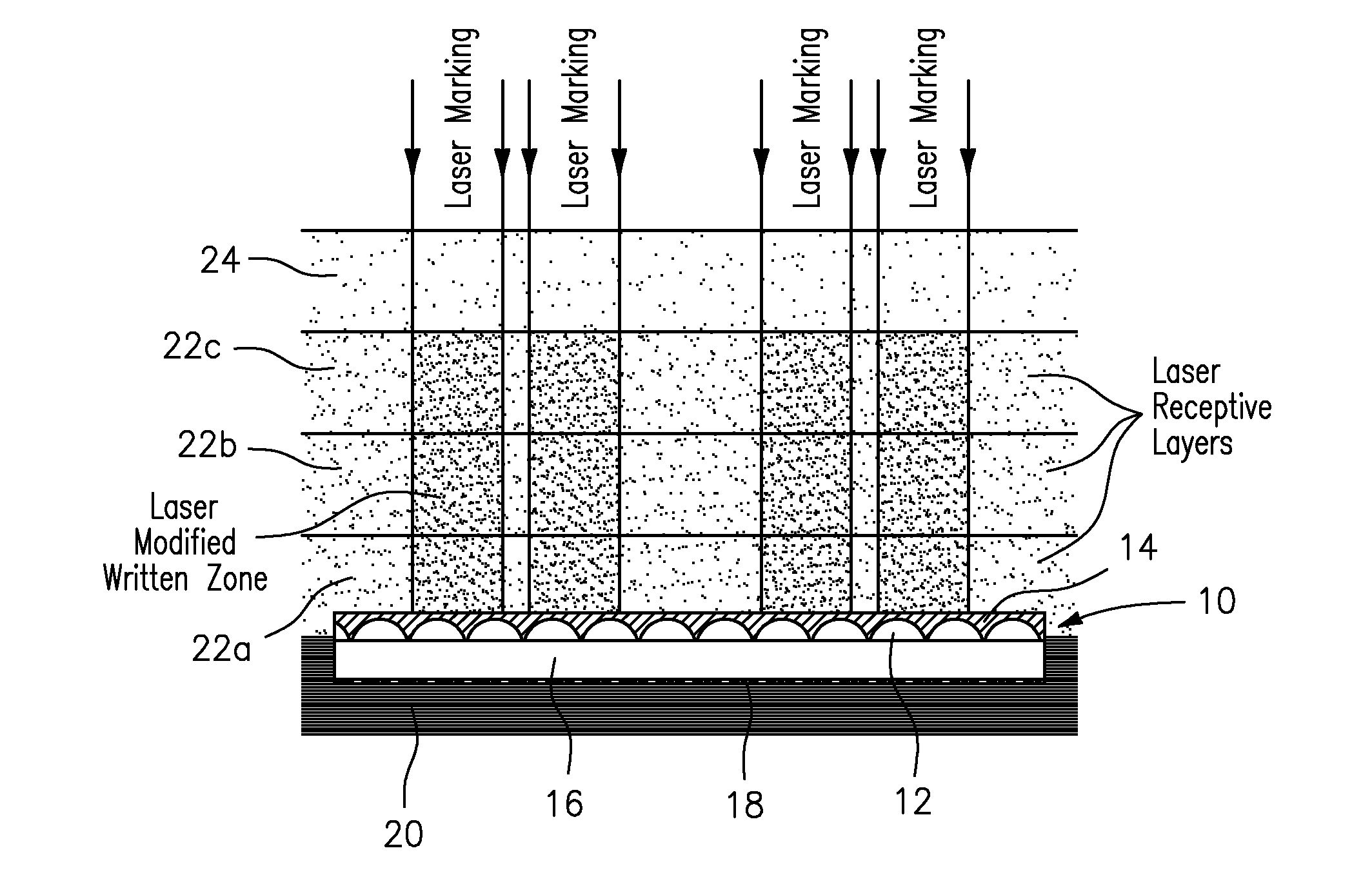
[0071]In this example, which is shown in FIG. 1, an optical film material 10 containing refractive lenses 12 encapsulated below a layer of a thermoset polymer 14, an optical spacer 16, and image icons 18 was prepared and then embedded between a 150 micron thick base layer 20 prepared using an opaque white polycarbonate film from SABIC with the product designation Lexan SD8B24 film, and a multi-layer construction made up of three laser markable layers 22a, 22b, 22c of 150 micron thick laser markable transparent polycarbonate film from SABIC with the product designation Lexan SD8B94 film, and a 150 micron thick outerlayer 24 prepared using a clear polycarbonate film from SABIC with the product designation Lexan SD8B14 film.

[0072]An image was then marked in the laser markable transparent polycarbonate film layers 22a, 22b, 22c using a V-Lase 10 Watt Q-switched 1064 nm laser marking system, which produced laser light emission at 30,000 Hz with a power setting of 80%, and scan speed of 2...

example 2

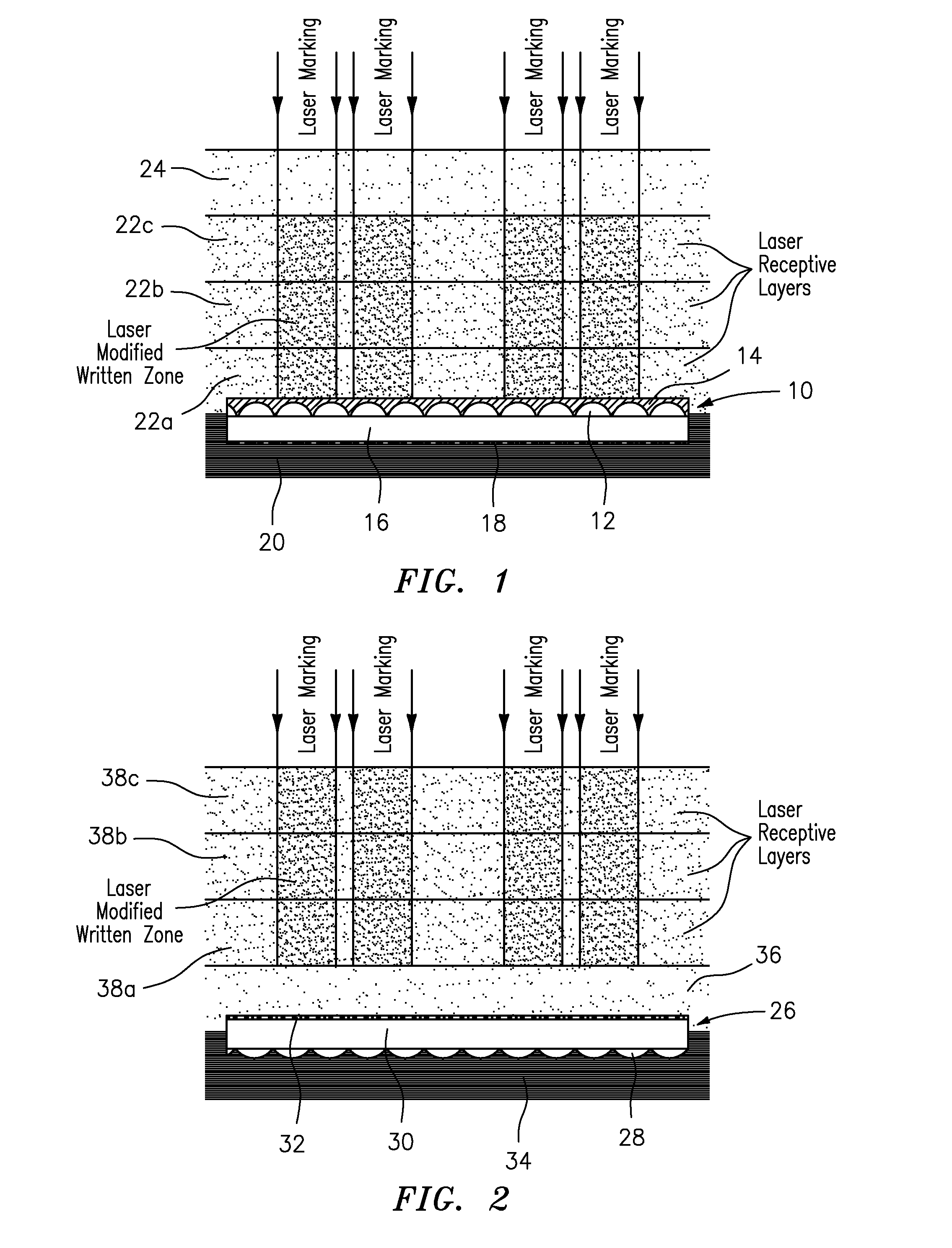
[0073]In this example, which is shown in FIG. 2, an optical film material 26 containing metalized reflective lenses 28, an optical spacer 30, and image icons 32 was prepared and then embedded between a 150 micron thick Lexan SD8B24 opaque white polycarbonate film base layer 34, and a multi-layer construction made up of a 150 micron thick Lexan SD8B14 clear polycarbonate innerlayer 36, and three 150 micron thick Lexan SD8B94 laser markable transparent polycarbonate film overlayers 38a, 38b, 38c.

[0074]An image was then marked in the laser markable transparent polycarbonate film layers 38a, 38b, 38c using the same laser marking system and settings as set forth above in Example 1. The resulting material or device again contained the laser marked image with no detectable damage to the optical film material or internal interfaces.

example 3

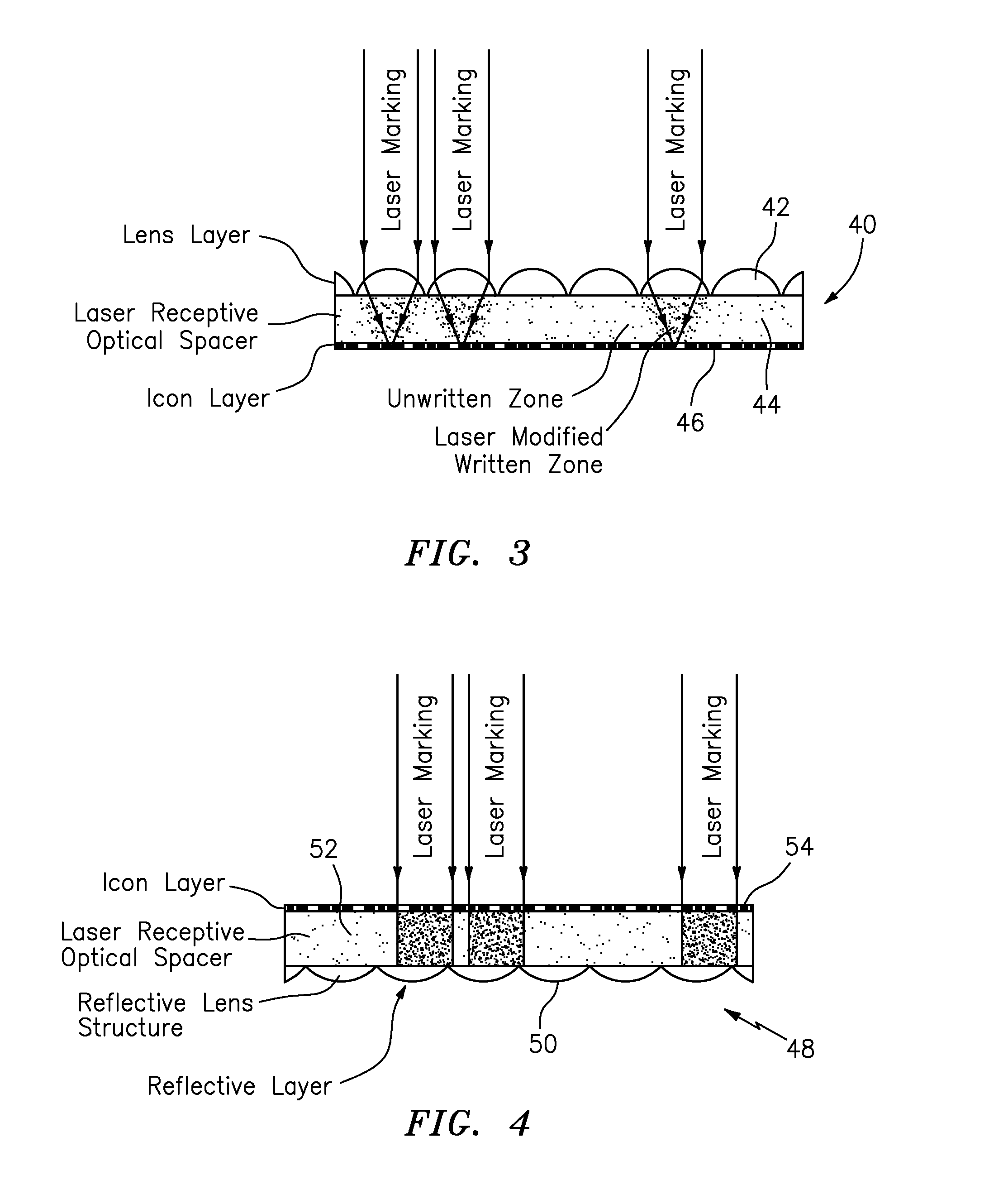
[0075]In this example, which is shown in FIG. 3, an optical film material 40 containing refractive lenses 42, a laser markable optical spacer 44, and image icons 46 was prepared. The laser markable optical spacer 44 was a 50 micron thick, clear polycarbonate sheet from 3M, 3M Center, St. Paul, Minn. 55144-100 (“3M”) under the product designation Clear LE clear polycarbonate film. An array of refractive lenses 42 with a 58 micron focal length were formed on an uppermost surface of the optical spacer 44, and a 3 micron thick arrangement or layer of pigmented image icons 46 was formed on the lowermost surface of the optical spacer 44. The prepared micro-optic film material projected synthetically magnified images with sharp focus.

[0076]An image was marked in the optical spacer 44 using the same laser marking system and settings as set forth above in Example 1. The resulting material or device contained the laser marked image with no detectable damage to the refractive lenses 42. In thi...


PUM

PropertyMeasurementUnit
thicknessaaaaaaaaaa
thicknessesaaaaaaaaaa

Abstract

An optical device projecting one or more synthetically magnified images that has been laser marked with one or more static two dimensional (2D) images is provided. The static 2D image(s) laser marked on or within this device and the synthetically magnified image(s) projected by this device help determine the authenticity of a document (e.g., passport data page) or product that employs it. Several embodiments of the inventive device also offer increased resistance to tampering or alteration and wear.

Description

RELATED APPLICATION[0001]This application claims priority to U.S. Provisional Patent Application Ser. No. 61 / 437,157, filed Jan. 28, 2011, which is incorporated herein in its entirety by reference.TECHNICAL FIELD[0002]The present invention generally relates to a laser marked device, and more particularly relates to an optical device projecting one or more synthetically magnified images that has been laser marked with one or more static two dimensional (2D) images.BACKGROUND AND SUMMARY OF THE INVENTION[0003]Micro-optic film materials projecting synthetic images generally comprise (a) a light-transmitting polymeric substrate, (b) an arrangement of micro-sized image icons located on or within the polymeric substrate, and (c) an arrangement of focusing elements (e.g., microlenses). The image icon and focusing element arrangements are configured such that when the arrangement of image icons is viewed through the arrangement of focusing elements, one or more synthetic images are projecte...

Claims


Application Information

Patent Timeline
Patent Type & Authority Applications(United States)
IPC IPC(8): G02B27/10F27D11/00
CPCB41M5/267G07D7/0006G02B3/0056B42D25/324B42D25/29B42D25/41B41M5/26G07D7/003
Inventor CAPE, SAMUEL M.GOSNELL, JONATHAN D.HELMINEN, KAJ MARKKUSJORDAN, GREGORY R.PALM, SCOTT K.PRETT, GILES D.SCHNEIDER, TIMOTHY W.ZUCCHERO, ANTHONY J.
Owner VISUAL PHYSICS LLC (US)
Why Eureka
Try Eureka