Systems and methods for dynamic threshold adjustment with primary-side sensing and regulation for flyback power converters

Active Publication Date: 2012-08-02
ON BRIGHT ELECTRONICS SHANGHAI
View PDF6 Cites 94 Cited by
  • Summary
  • Abstract
  • Description
  • Claims
  • Application Information

AI Technical Summary

Benefits of technology

[0035]Many benefits are achieved by way of the present invention over conventional techniques. Certain embodiments of the present invention dynamically adjust the on-time duration with pulse-frequency modulation. Some embodimen

Problems solved by technology

But the power conversion system 300 or 400 often canno

Method used


Image

  • Systems and methods for dynamic threshold adjustment with primary-side sensing and regulation for flyback power converters
  • Systems and methods for dynamic threshold adjustment with primary-side sensing and regulation for flyback power converters
  • Systems and methods for dynamic threshold adjustment with primary-side sensing and regulation for flyback power converters

Examples


Embodiment Construction

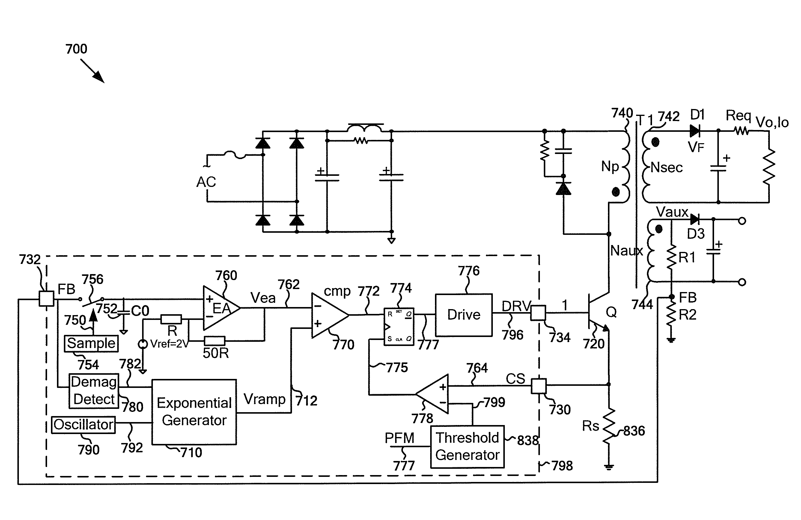
[0053]The present invention is directed to integrated circuits. More particularly, the invention provides dynamic threshold adjustment for over-current protection. Merely by way of example, the invention has been applied to a flyback power converter. But it would be recognized that the invention has a much broader range of applicability.

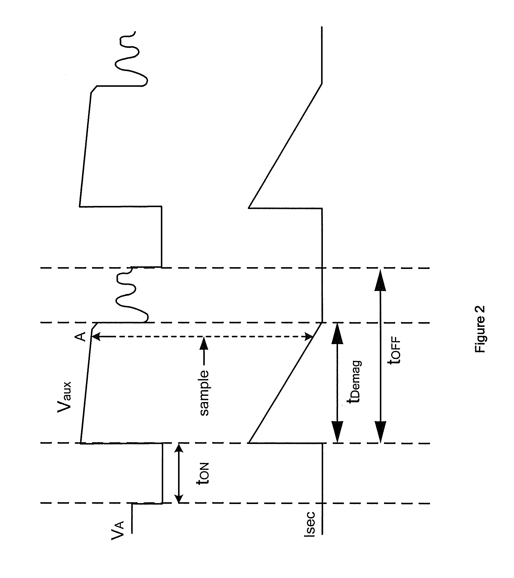
[0054]Referring to FIGS. 3 and 4, in the discontinuous conduction mode (DCM), the energy transfer relationship for the flyback power conversion system 300 or 400 is

Po=½×L×I2p×Fs×η  (Equation 6)

[0055]where Po represents the output power of the system 300 or 400. Additionally, L represents the conductance of the primary winding 340 or 440, and Ip represents the peak current of the primary winding 340 or 440. Moreover, Fs represents the switching frequency of the power switch 320 or 420, and η represents the conversion efficiency of the system 300 or 400. Furthermore,

Ip=VthocRs(Equation7)

[0056]where Vthoc represents the magnitude of the threshold signal...


PUM


Abstract

System and method for adjusting a threshold of a power conversion system. The system includes a threshold generator configured to receive a first signal and generate a threshold signal based on at least information associated with the first signal, a comparator configured to receive the threshold signal and a second signal and generate a comparison signal, and a gate driver configured to generate a drive signal based on at least information associated with the comparison signal. The gate driver is coupled to at least a switch configured to receive the drive signal and affect a current flowing through a primary winding coupled to a secondary winding. If the second signal is larger than the threshold signal in magnitude, the drive signal causes the switch to open. The drive signal is associated with a switching frequency.

Description

1. CROSS-REFERENCES TO RELATED APPLICATIONS[0001]This application claims priority to Chinese Patent Application No. 201110034669.9, filed Feb. 1, 2011, commonly assigned, incorporated by reference herein for all purposes.[0002]Additionally, this application is related to U.S. patent application Ser. No. 12 / 859,138, commonly assigned, incorporated by reference herein for all purposes.2. BACKGROUND OF THE INVENTION[0003]The present invention is directed to integrated circuits. More particularly, the invention provides dynamic threshold adjustment for over-current protection. Merely by way of example, the invention has been applied to a flyback power converter. But it would be recognized that the invention has a much broader range of applicability.[0004]Generally, a conventional power conversion system often uses a transformer to isolate the input voltage on the primary side and the output voltage on the secondary side. To regulate the output voltage, certain components, such as TL431 ...

Claims


Application Information

Patent Timeline
IPC IPC(8): H02M3/335H02M1/00
CPCH02M2001/0003H02M3/33523G05F1/00G05F1/10H02M1/0003H02M1/08H02M3/335H02M3/33592
Inventor ZHANG, YUNCHAODONG, JINYAZHANG, XIUHONGFANG, LIEYI
Owner ON BRIGHT ELECTRONICS SHANGHAI
Why Eureka
Try Eureka