Plastic material injection molding system

Inactive Publication Date: 2012-08-02
QUANTA COMPUTER INC
View PDF24 Cites 5 Cited by
  • Summary
  • Abstract
  • Description
  • Claims
  • Application Information

AI Technical Summary

Benefits of technology

[0015]To sum up, since the plastic material injection molding system of the invention is designed for decreasing flow speed and boosting pressure of the liquid plastic material, the liquid plastic material can be filled in the forming cavity un...

Problems solved by technology

Therefore, since the plastic product made by the conventional injection molding method mentioned above still obviously exist...

Method used


Image

  • Plastic material injection molding system
  • Plastic material injection molding system
  • Plastic material injection molding system

Examples


Embodiment Construction

[0021]In the following detailed description, for purposes of explanation, numerous specific details are set forth in order to provide a thorough understanding of the disclosed embodiments. It will be apparent, however, that one or more embodiments may be practiced without these specific details. In other instances, well-known structures and devices are schematically shown in order to simplify the drawings.

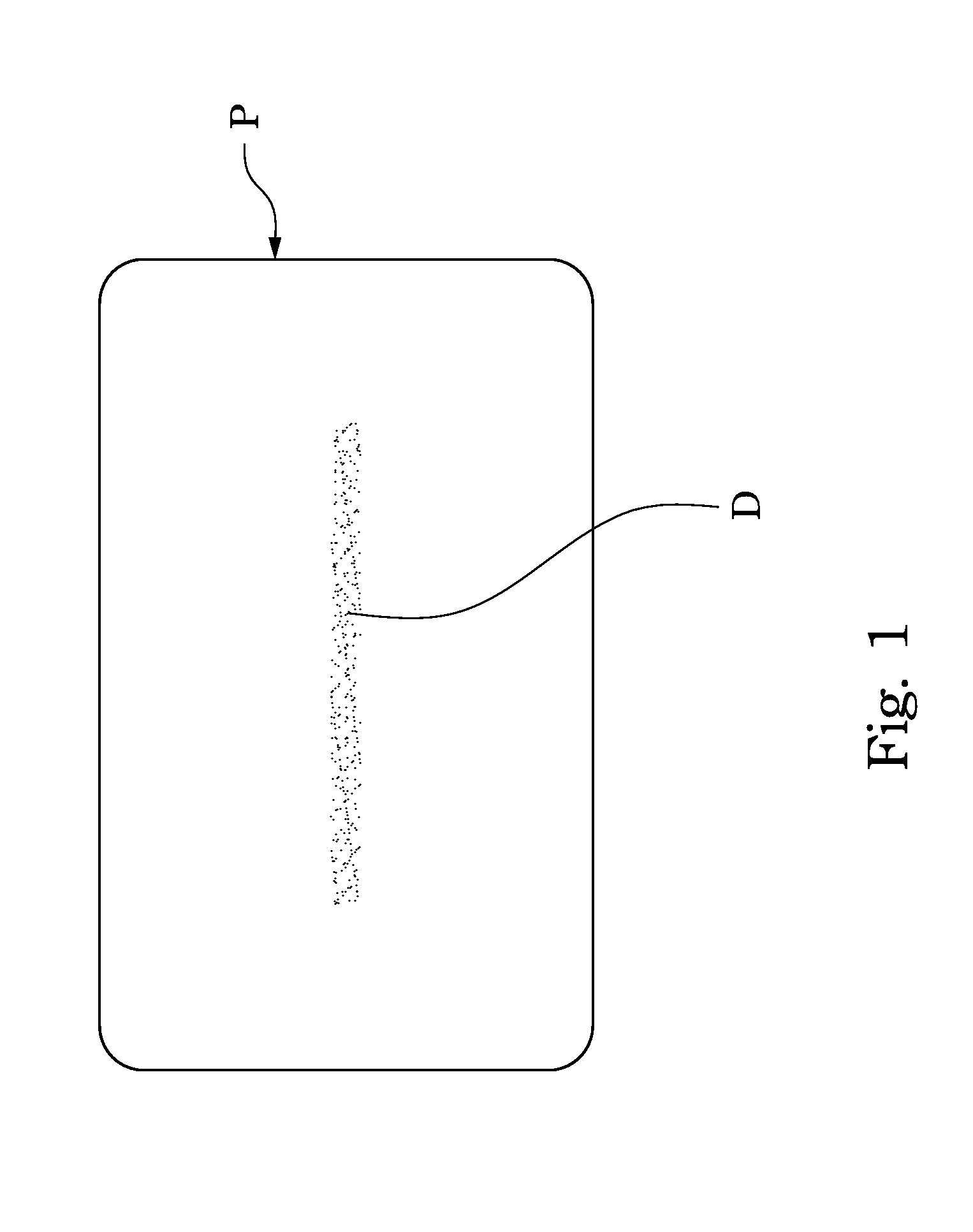
[0022]Since the plastic product P made by the conventional injection molding method mentioned above always exists with imperfections of the feeding-point shadow D (FIG. 1) on the surface of the plastic product P, thus, the feeding-point shadow D is with a darker color so as to cause uneven quality of color on the integral appearance. Therefore, after analyzing and researching constantly by the inventor of the present invention, the inventor has found the main reason why the feeding-point shadow D generated on the surface of the plastic product P, that is, the boosting pressure of t...


PUM


Abstract

A plastic material injection molding system includes a feeding nozzle, a forming mold having a cave therein, and a material-passing mold having a runner therein. The runner communicates both the feeding nozzle and the cave, and has two curved parts therein for slowing down the plastic material injected from the feeding nozzle in order.

Description

RELATED APPLICATIONS[0001]This application claims priority to Taiwanese Application Serial Number 100103918, filed Feb. 1, 2011, which is herein incorporated by reference.BACKGROUND[0002]1. Technical Field[0003]The present invention relates to a molding system, more particular to a plastic material injection molding system.[0004]2. Description of Related Art[0005]In a process of making a plastic product by a conventional injection molding method, mold designs, plastic material qualities, plastic material feeding pressures or internal parameters (e.g. time, temperature, pressure, flow speed) of plastic material in mold may be one of the factors for the plastic product to be imperfect. Commonly, these imperfections can be wrinkles, blisters, scrapes, granulations or feeding-point shadows formed on a surface of the plastic product etc.[0006]Refer to FIG. 1 in which FIG. 1 is a top view of a plastic product P made by a conventional injection molding method. Regarding to the so-called fe...

Claims


Application Information

Patent Timeline
IPC IPC(8): B29C45/03
CPCB29C45/2703B29C45/27
Inventor WU, HSIEN-MINGLIN, CHAO-HUNG
Owner QUANTA COMPUTER INC
Why Eureka
Try Eureka