Inflatable Retention System for Enteral Feeding Device

a technology of inflatable retention and indwelling catheter, which is applied in the field of improved devices for retaining indwelling catheters or tubes, can solve the problems of changing the dimensions of balloons, reducing the retention or resistance of balloons, and reducing the ability of balloons to be inserted and removed through the stoma, so as to achieve less elastic

Active Publication Date: 2012-08-02
AVENT INC
View PDF13 Cites 5 Cited by
  • Summary
  • Abstract
  • Description
  • Claims
  • Application Information

AI Technical Summary

Benefits of technology

[0118]Another advantage of the invention is minimal impact of the contribution of the balloon to the effective outside diameter of the feed tube between the attachment locations of the balloon. Due to its thin wall, the completely deflated balloon folds and wraps around the feeding tube with negligible thickness contributions. Table 13 illustrates the effects that deflated balloons contribute to effective outside diameters for balloon catheters per measurements made on Samples D, M, and A. Each sample had five measurements made using calipers capable of discerning 0.0001 inch increments in regions without any attached balloons and in regions of attached and completely deflated balloons. The measurements of the feed tubes without attached balloons were averaged to give the Catheter Diameter (C) values in Table 13; those measurements of the feed tubes between balloon attachment locations with completely deflated balloons were averaged to give the Catheter Diameter+Balloon (C+B) values. The ratios of C+B / C in Table 13 clearly show that the balloons suitable for the invention have less impact on the effective outside feed tube diameter than conventional catheters with balloons.

Problems solved by technology

While these balloons have many advantages, these balloons generally provide a much lower level of retention or resistance to being pulled out through the stoma.
Elastomeric or “soft” medical grade silicone has a tendency to “creep” or stress relax over time which can change the dimensions of the balloon.
In addition, the thickness of these balloons can make it more difficult to insert and remove an uninflated balloon through the stoma.
However, such devices have unsatisfactory thickness in the region of the balloon that makes it difficult to insert the device through a stoma.
Moreover, the relationship between the amount of pressure needed to stretch such elastic materials to expand the balloon and the volume of the balloon is nonlinear.

Method used


Image

  • Inflatable Retention System for Enteral Feeding Device
  • Inflatable Retention System for Enteral Feeding Device
  • Inflatable Retention System for Enteral Feeding Device

Examples


example 1

Retention Testing

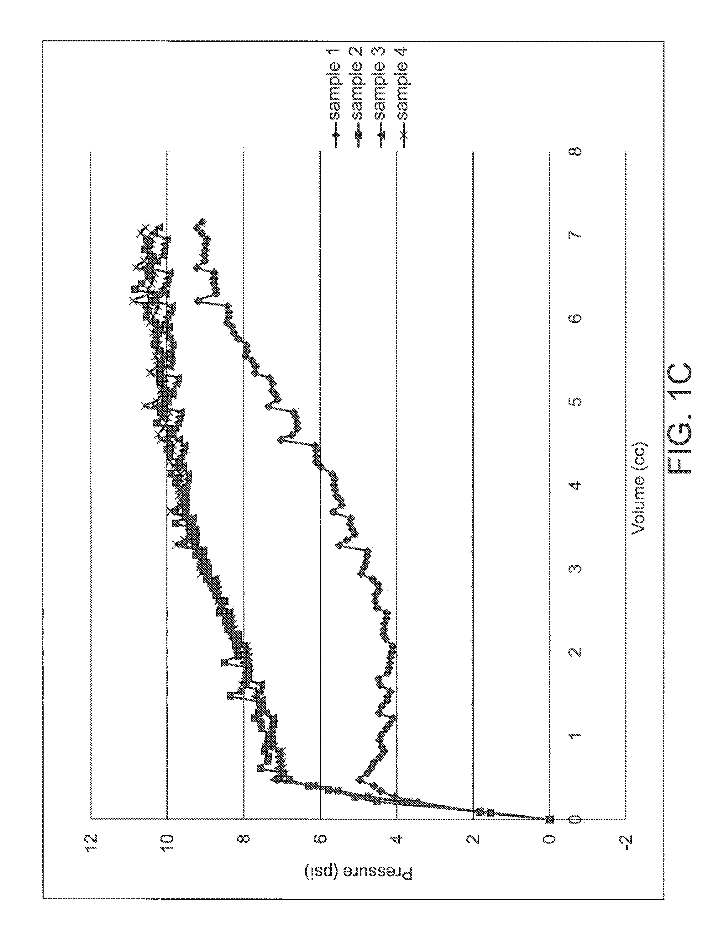
[0092]Samples of different enteral feeding tube devices that utilize different retention mechanisms were tested according to the Retention Test Procedure described above using the MTS Alliance RT / 5 (DVC068-01) tensile tester and 250 N load cell (DVC068-06). Approximately 10 specimens of each sample were used except for Sample 2 (which has only one specimen) and an average value for the peak load (referred to as “retention force”) was determined.

[0093]The following comparative samples were tested:

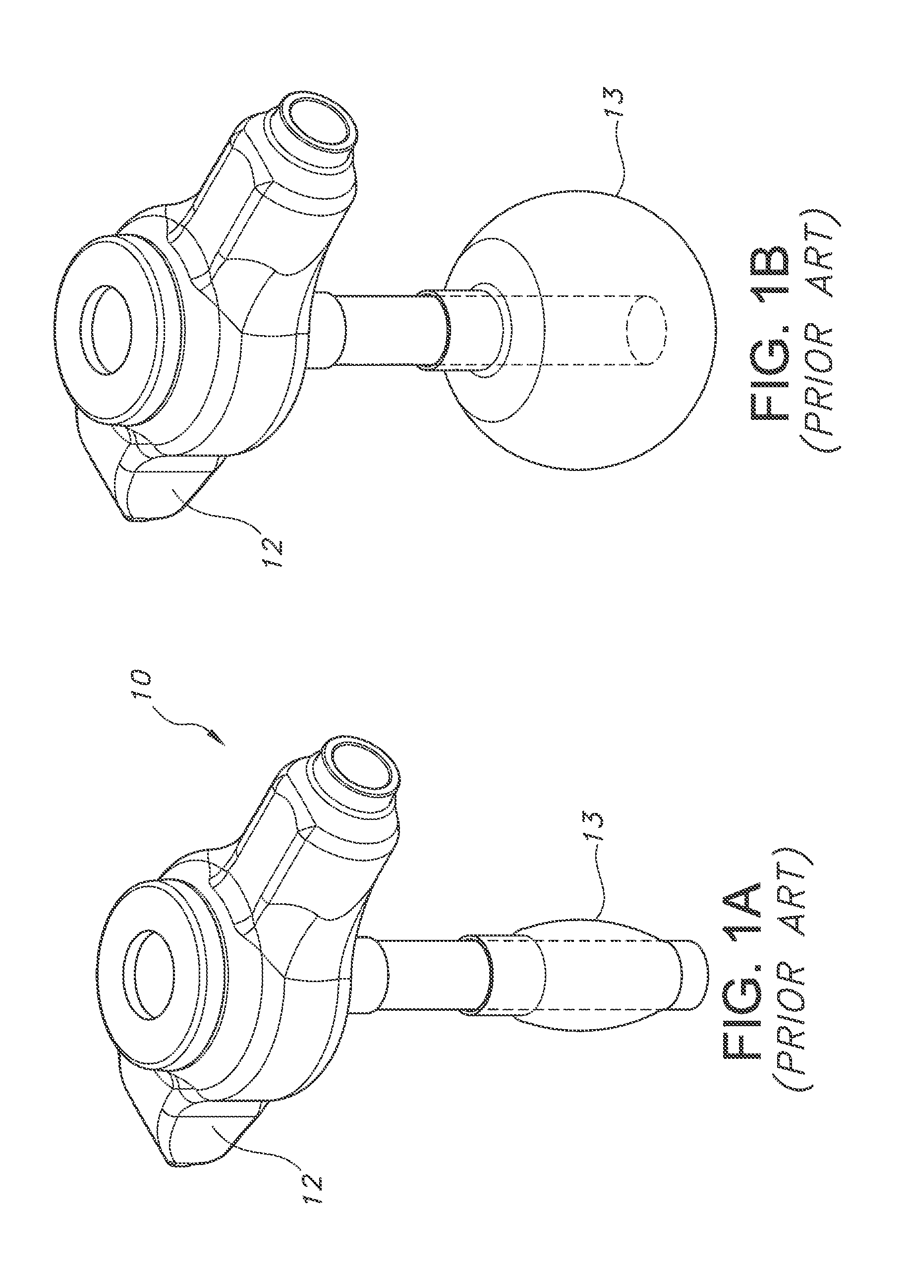
[0094]Sample 1—Kimberly-Clark MIC-KEY® low profile enteral feeding tube with silicone balloon—molded to be apple shaped. Size 16 French (16 Fr) feeding tube. The balloon was filled with 5 milliliters of water. During testing, the silicone balloon deformed at peak load (i.e., the “retention force”) and the device pulled through the retention plate fully intact.

[0095]Sample 2—Kimberly-Clark MIC-KEY® low profile enteral feeding tube with silicone balloon—molded to be generally ...

example 2

Retention Diameter / Tube Diameter

[0106]The maximum diameter in the perpendicular direction from the axis of the tube of each retention portion of the Samples from Example 1 (with the exception of Sample 2) was measured. For the devices that require inflation, the devices were inflated with the volume of water specified in Example 1 with the exception of Samples 10 and 11 which were inflated to a diameter of 12 millimeters which represents the fully extended or distended state of the balloon on that device. The diameter of the tube was measured in a region where the balloon or other retention device was not attached. The diameter of each tube was uniform along the length of the tube. The retention diameter was divided by the tube diameter and the ratio is reported in Table 4.

TABLE 4RetentionRetentionTubeDiameter-TubeDeviceDiameterDiameterDiameter RatioSample 1 - 16Fr Silicone20.4 mm5.33 mm3.83Balloon, apple shapedSample 2 - 18Fr SiliconeSample  6 mmN.A.Balloon, disc shapeddestroyeddur...

example 3

Balloon Stability

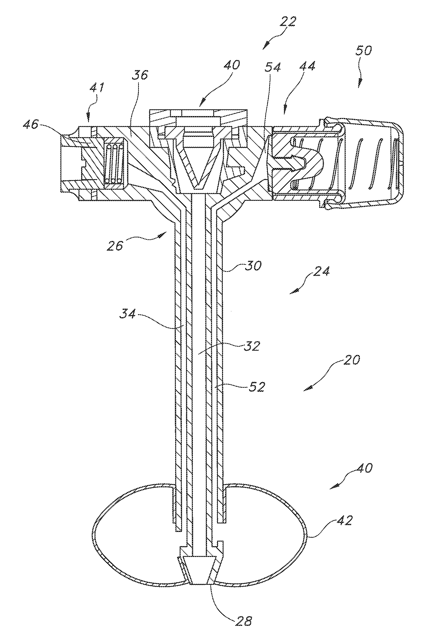
[0107]The balloon used as the retention component in the invention has a shape that is generalized as an oblate spheroid like other balloons used for enteral feed tubes. This shape is different from cylinder-like ones that are typical for vascular catheters, e.g. angioplasty catheters. As described previously, such generalized oblate spheroid shapes have characterizing diameters along their minor and major axes. For purposes of this Example, the greatest distance of the spheroid in the direction of its minor axis is termed the polar diameter (P) and the largest diameter in the direction of its major axis (orthogonal to the minor axis) is termed an equatorial diameter (E). In keeping with previous preferred descriptions but using the terminology of this Example, preferred shapes of the balloons of the invention have polar diameters that are significantly less than their equatorial diameters.

[0108]In making the balloons used in the invention, the balloons are preforme...


PUM


Abstract

An inflatable retention system for an enteral feeding tube having a base deployed outside the human body and an indwelling retainer which is deployed within a lumen or cavity of the body by insertion through a stoma from outside the body. The retention system includes a tube having a proximal end, a distal end, an external tube diameter, and tube walls defining a feeding lumen and an inflation lumen. The retention system also includes an inflatable balloon located at a distal end of the tube in fluid communication with the inflation lumen, the balloon having thin, flexible walls, a predetermined spheroid shape, and a volume at which a fluid in the balloon is under no pressure such that upon inflation with a fluid to pressurize fluid in the balloon, the balloon assumes a stable spheroid shape and exhibits a substantially linear pressure versus volume curve.

Description

[0001]The present application is a Divisional of U.S. patent application Ser. No. 12 / 977,945, filed on Dec. 23, 2010, and claims priority thereto.FIELD OF THE INVENTION[0002]The present invention relates to improved device for retaining an indwelling catheter or tube. More particularly, the present invention relates to a device for retaining gastrostomy tubes or enteral feeding catheters having a base deployed outside the human body and a retainer which is inserted through a stoma from outside the body for deployment within a lumen of the body.BACKGROUND[0003]Numerous situations exist in which a body cavity needs to be catheterized to achieve a desired medical goal. One relatively common situation is to provide nutritional solutions or medicines directly into the stomach or intestines. A stoma is formed in the stomach or intestinal wall and a tube is placed through the stoma. This surgical opening and / or the procedure to create the opening is common referred to as “gastrostomy”. Fee...

Claims


Application Information

Patent Timeline
Patent Type & Authority Applications(United States)
IPC IPC(8): A61M25/10A61F2/958
CPCA61J15/0015A61J15/0042A61J2015/0088A61J15/0049A61J15/0065A61J15/0092A61J15/0069A61J15/0088
Inventor BAGWELL, ALISON S.ESTES, THOMAS G.MCMICHAEL, DONALD J.ROTELLA, JOHN A.TEIXEIRA, SCOTT M.
Owner AVENT INC
Why Eureka
Try Eureka