Machine tool control system

a control system and machine tool technology, applied in the direction of program control, total factory control, instruments, etc., can solve the problems of reducing the unable to calculate the limit of the torque generated, and the finishing shape of the work tends to deviate from the intended design, so as to improve the machining accuracy of the machine tool, the effect of reducing the machining time and increasing the operating speed

Inactive Publication Date: 2012-08-02
DMG MORI SEIKI CO LTD
View PDF12 Cites 5 Cited by
  • Summary
  • Abstract
  • Description
  • Claims
  • Application Information

AI Technical Summary

Benefits of technology

[0012]In the machine tool control system according to the present invention, the CL data inclusive of the tool path is generated by the CL data generating unit based on the shape data regarding the post-machining shape of the work. The cutting feed rate data in each part on the tool path of the CL data is then generated by the cutting feed rate generating unit based on the CL data and the driving capability data regarding the driving capability of the driving unit of the machine tool. The controller then directly outputs the CL data and the cutting feed rate data to the driving unit of the machine tool. It is thus possible to cause relative movement between the work and the tool at an optimum cutting feed rate at each part of the tool path along the tool path.
[0013]Thus, with the control system for the machine tool according to the present invention, the operating speed may be higher than in the conventional system to reduce the machining time. Moreover, in the machine tool control system of the present invention, the as-machined work, for example, its corner, may be machined as intended by the designer, thereby improving machining accuracy of the machine tool.

Problems solved by technology

On the other hand, even though the limits of the acceleration and the speed of the driving unit that actuates the respective driving shafts may be known beforehand, there lack data on the mass weight or the inertial force of a moving object, such as a work, during the machining operations.
It is thus not possible to calculate the limit of the torque generated with acceleration beforehand.
Hence, the finishing shape of the work tends to deviate from what has been intended by the designer.
In addition, since the R produced at the corner of the work is set in a sloppy manner, there persists a problem that the final shape may not be surmised until the time the work has ultimately been cut.

Method used


Image

  • Machine tool control system
  • Machine tool control system
  • Machine tool control system

Examples


Embodiment Construction

[0026]The machine tool control system according to the present invention will now be described in detail with reference to the drawings.

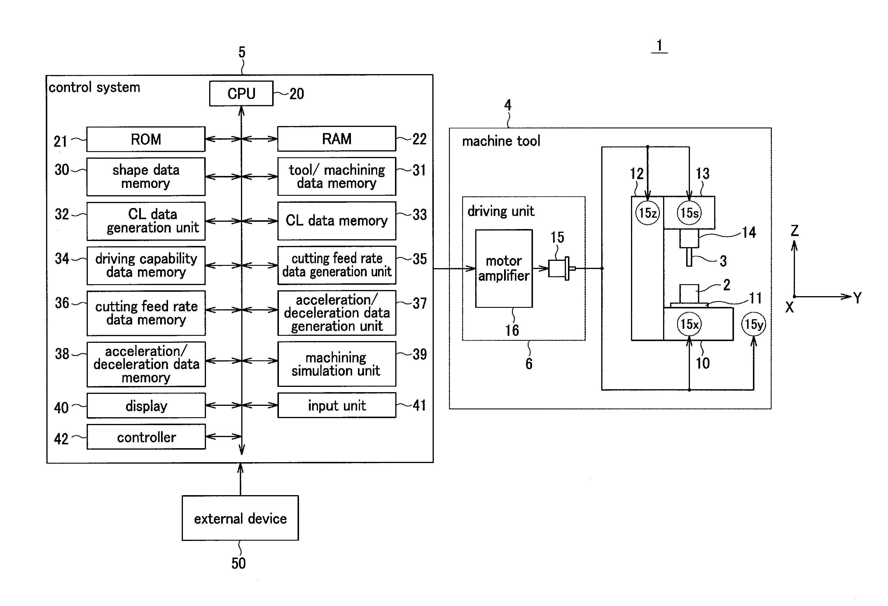
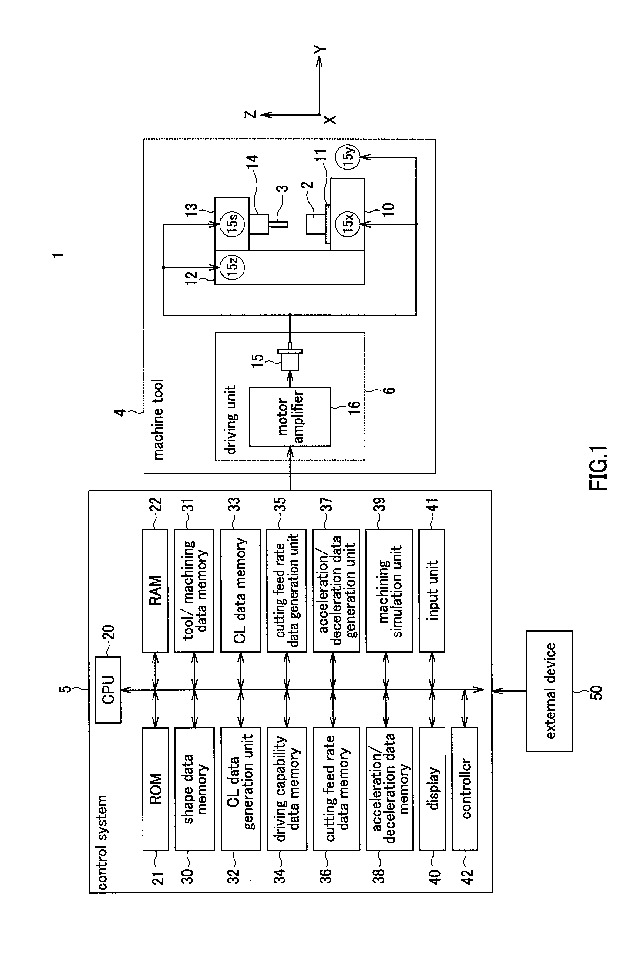
[0027]FIG. 1 depicts a block diagram showing an arrangement of a system for machining operations 1 provided with the machine tool control system according to the present invention. Referring to FIG. 1, the system for machining operations 1 includes a machine tool 4, and a control system 5 that controls the machine tool 4. In the machining system 1, a work 2 as an object of the machining operations is cut to a desired shape with a cutting tool 3 as the work 2 and the cutting tool 3 are moved relative to each other.

[0028]The machine tool 4 is a vertical type machining center having three linear driving axes, that is, X-, Y- and Z-axes, perpendicular to one another, as shown in FIG. 1. Specifically, the machine tool 4 includes a machine table 11, a machining head 13 and a main spindle 14. The machine table 11 is movably carried on a head 10, as a suppo...


PUM


Abstract

An optimum cutting feed rate of a machine tool is calculated at the outset and a tool path as well as the optimum cutting feed rate calculated is directly output to a driving unit of the machine tool. A relative movement between the work and a tool is made to occur along the tool path at the optimum cutting feed rate for each part of the tool path. To this end, a control system includes a CL data generating unit 32, a CL data memory 33, a driving capability data memory 34, a cutting feed rate data generation unit 35, a cutting feed rate data memory 36, and a controller 42.

Description

BACKGROUND OF THE INVENTION[0001]1. Field of the Invention[0002]This invention relates to a control system for a machine tool in which an optimum feed rate of cutting of the machine tool is calculated at the outset, a tool path as well as an optimum feed rate of cutting calculated is directly output to a driving unit of the machine tool, and in which a work and the tool are relatively moved along the tool path at an optimum cutting feed rate at each part of the tool path.[0003]2. Description of Related Art[0004]A conventional machine tool includes a CNC controller that controls the driving of the driving motor based on NC data composed of NC programs termed ‘G code’. If, in such conventional machine tool, a free curved surface, for example, is to be cut, an operating command is issued at each of a number of extremely short line segments, as shown in Patent publication 1. The CNC controller is instructed by NC data so as to render the cutting feed rate constant. On receiving the NC d...

Claims


Application Information

Patent Timeline
Patent Type & Authority Applications(United States)
IPC IPC(8): G05B19/4099
CPCG05B19/40932Y02P90/02
Inventor KIMURA, AKIRAONO, KATSUHIKO
Owner DMG MORI SEIKI CO LTD
Why Eureka
Try Eureka