
Exploitation of self-consistency and differences between volume images and interpreted spatial/volumetric context

a technology of applied in the field of self-consistency and differences between volume images and spatial/volumetric context, can solve the problems of inability to quantitatively define well, each process step has inherent uncertainties and non-uniqueness that cannot be reconciled/integrated and it is difficult to quantify the uncertainties and non-uniqueness of geological reservoir models yielded by conventional industry workflows. , to achieve the effect of improving the accuracy

Inactive Publication Date: 2012-08-02
CHEVROU USA INC
View PDF4 Cites 27 Cited by
  • Summary
  • Abstract
  • Description
  • Claims
  • Application Information

AI Technical Summary

Benefits of technology

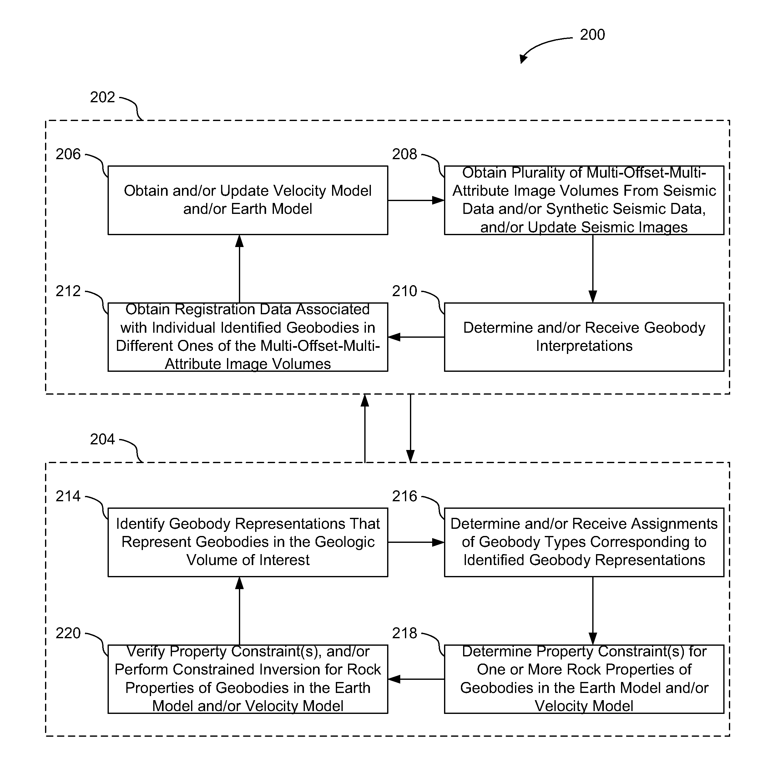
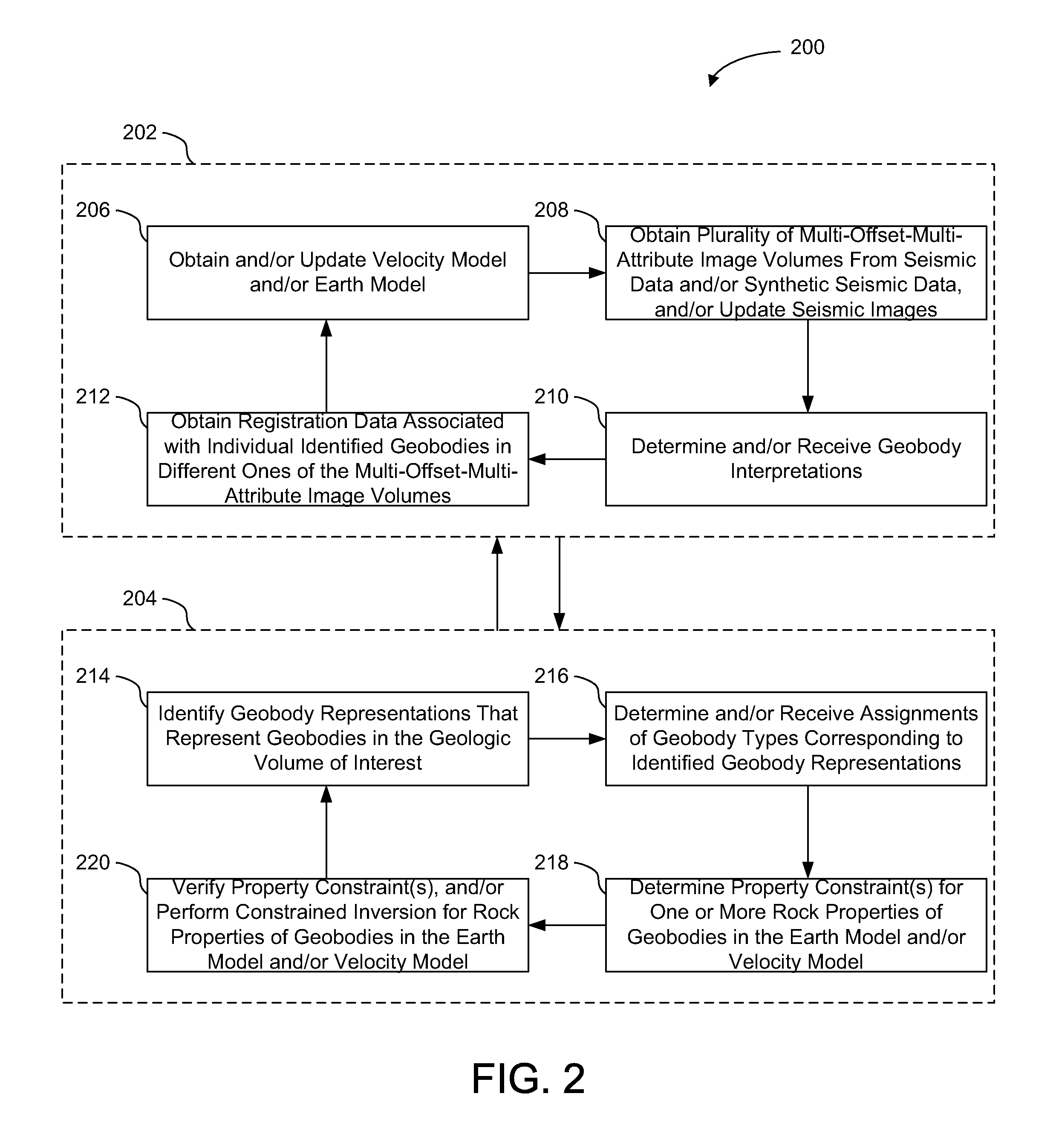
[0004]One aspect of the disclosure relates to a computer-implemented method for exploiting positional and / or shape discrepancies and / or similarities of geobodies in image volumes associated with earth models of a geologic volume of interest to improve the accuracy of the earth models, velocity models used for pre-stack imaging, and / or the image volumes. The method may include obtaining a velocity model and / or an earth model from seismic data representing energy that has propagated through the geologic volume of interest from one or more energy sources to one or more energy receivers. The seismic data may include one or more of a plurality of offset stacks, a plurality of angle stacks, or a plurality of azimuth stacks. The method may include obtaining a plurality of multi-offset-multi-attribute image volumes from the seismic data. A given one of the multi-offset-multi-attribute image volumes may (1) correspond to one of the offset stacks, angle stacks, or azimuth stacks, (2) be associated with at least one attribute, and (3) include geobody representations of geobodies present in the geologic volume of interest. The method may include receiving geobody interpretations based on the multi-offset-multi-attribute image volumes. The geobody interpretations may include identified geobodies having geobody representations in the multi-offset-multi-attribute image volumes and geobody types assigned to the identified geobodies. The method may include obtaining registration data associated with individual identified geobodies in different ones of the multi-offset-multi-attribute image volumes based on the assigned geobody types. The registration data for a given geobody may represent a spatial position, a shape of the given geobody, and / or discrepancies and / or similarities between geobody representations of the given geobody in different ones of the multi-offset-multi-attribute image volumes. The method may include updating the earth model and / or the velocity model using travel time inversion techniques based on the registration data and the assigned geobody types. The method may include generating updated multi-offset-multi-attribute image volumes based on the updated earth model and / or the updated velocity model.
[0006]Yet another aspect of the disclosure relates to a computer-readable medium having instructions embodied thereon. The instructions may be executable by a processor to perform a method for exploiting positional and / or shape discrepancies and / or similarities of geobodies in image volumes associated with earth models of a geologic volume of interest to improve the accuracy of the earth models, velocity models used for pre-stack imaging, and / or the image volumes. The method may include obtaining a velocity model and / or an earth model from seismic data representing energy that has propagated through the geologic volume of interest from one or more energy sources to one or more energy receivers. The seismic data may include one or more of a plurality of offset stacks, a plurality of angle stacks, or a plurality of azimuth stacks. The method may include obtaining a plurality of multi-offset-multi-attribute image volumes from the seismic data. A given one of the multi-offset-multi-attribute image volumes may (1) correspond to one of the offset stacks, angle stacks, or azimuth stacks, (2) be associated with at least one attribute, and (3) include geobody representations of geobodies present in the geologic volume of interest. The method may include receiving geobody interpretations based on the multi-offset-multi-attribute image volumes. The geobody interpretations may include identified geobodies having geobody representations in the multi-offset-multi-attribute image volumes and geobody types assigned to the identified geobodies. The method may include obtaining registration data associated with individual identified geobodies in different ones of the multi-offset-multi-attribute image volumes based on the assigned geobody types. The registration data for a given geobody may represent a spatial position, a shape of the given geobody, and / or discrepancies and / or similarities between geobody representations of the given geobody in different ones of the multi-offset-multi-attribute image volumes. The method may include updating the earth model and / or the velocity model using travel time inversion techniques based on the registration data and the assigned geobody types. The method may include generating updated multi-offset-multi-attribute image volumes based on the updated earth model and / or the updated velocity model.

Problems solved by technology

Conventional industry workflows have limited reconciliation / integration of earth models used in imaging with interpretation of structure and stratigraphy, and with reservoir properties from seismic estimation.
Each process step has inherent uncertainties and non-uniqueness that cannot be well defined quantitatively.
Consequently, it is difficult to quantify the uncertainties and non-uniqueness of geological reservoir models yielded by conventional industry workflows.
Even so, there is no guarantee that the resulting, probabilistic models are consistent with all the data utilized in generating the models.

Method used


Image

  • Exploitation of self-consistency and differences between volume images and interpreted spatial/volumetric context
  • Exploitation of self-consistency and differences between volume images and interpreted spatial/volumetric context
  • Exploitation of self-consistency and differences between volume images and interpreted spatial/volumetric context

Examples


Embodiment Construction

[0010]The present technology may be described and implemented in the general context of a system and computer methods to be executed by a computer. Such computer-executable instructions may include programs, routines, objects, components, data structures, and computer software technologies that can be used to perform particular tasks and process abstract data types. Software implementations of the present technology may be coded in different languages for application in a variety of computing platforms and environments. It will be appreciated that the scope and underlying principles of the present technology are not limited to any particular computer software technology.

[0011]Moreover, those skilled in the art will appreciate that the present technology may be practiced using any one or combination of hardware and software configurations, including but not limited to a system having single and / or multi-processor computer processors system, hand-held devices, programmable consumer el...


PUM


Abstract

Self-consistency and / or differences between volume images and interpreted spatial / volumetric context may be exploited for improving seismic imaging and estimation of attributes of geobodies, in accordance with one or more embodiments. Exemplary embodiments allow exploitation of positional and / or shape discrepancies and / or similarities of geobodies in image volumes associated with a geologic model of a geologic volume of interest to improve the accuracy of the geologic model and / or the image volumes. Constraints associated with the geologic volume of interest may be determined and / or utilized to confirm and / or specify dependencies between attributes that are potentially associated with individual geobodies.

Description

FIELD OF THE DISCLOSURE[0001]This disclosure relates to improving seismic imaging and estimation of attributes and / or rock properties of geobodies by exploiting self-consistency and / or differences between volume images and interpreted spatial / volumetric context.BACKGROUND OF THE DISCLOSURE[0002]Seismic imaging and subsurface interpretation are performed to obtain, as accurately as possible, a geologic model of a subsurface volume of the earth. Conventional industry workflows generally include the following serial process steps: (a) process the seismic data into 3D seismic image volumes of the subsurface volume of the earth; (b) extract attributes (e.g., velocity, Poisson's ratio, density, acoustic impedance, etc.) at each subsurface point in the subsurface volume of the earth using tabulated and other known petrophysical data and rock properties; (c) interpret the geometry of the 3D seismic image volumes, log information, and geological analogs on an interpretation workstation to ob...

Claims


Application Information

Patent Timeline
Patent Type & Authority Applications(United States)
IPC IPC(8): G06G7/48
CPCG01V1/30
Inventor VU, CUNG KHACPOSAMENTIER, HENRY W.DISIENA, JAMES P.DYGERT, TODD
Owner CHEVROU USA INC
Learn More