Bus Clock Frequency Scaling for a Bus Interconnect and Related Devices, Systems, and Methods

a bus clock frequency and interconnect technology, applied in the field of electronic bus interconnects, can solve the problems of lowering the bus clock frequency, affecting the performance of the subsystem, so as to reduce or avoid the latencies of the bus clock frequency

Active Publication Date: 2012-08-02
QUALCOMM INC
View PDF5 Cites 44 Cited by
  • Summary
  • Abstract
  • Description
  • Claims
  • Application Information

AI Technical Summary

Benefits of technology

[0010]In another embodiment, a computer-readable medium is provided. The computer-readable medium has stored thereon computer executable instructions to cause a bus interconnect, comprising an interconnect network configurable to connect a master port among a plurality of master ports to a slave port(s), to scale (e.g., increase or decrease) the frequency of a bus interconnect clock signal generated by a controller and configured to clock the interconnect network in response to at least one of: (a) at least one first bandwidth information related to traffic communicated over the at least one master port meeting a respective at least one first bandwidth condition, and (b) at least one second bandwidth information related to traffic communicated over the at least one slave port meeting a respective at least one second bandwidth condition.
[0011]In other embodiments, the controller may also be configured to scale (e.g., increase or decrease) the frequency of the bus interconnect clock signal additionally only if the latency for the master port(s) meets a respective latency condition for the m

Problems solved by technology

However, lowering the bus clock frequency lowers performance of the bus interconnect.
If lowering the bus clock frequency increases bus latency beyond latency requirements or conditions for the sub

Method used


Image

  • Bus Clock Frequency Scaling for a Bus Interconnect and Related Devices, Systems, and Methods
  • Bus Clock Frequency Scaling for a Bus Interconnect and Related Devices, Systems, and Methods
  • Bus Clock Frequency Scaling for a Bus Interconnect and Related Devices, Systems, and Methods

Examples


Embodiment Construction

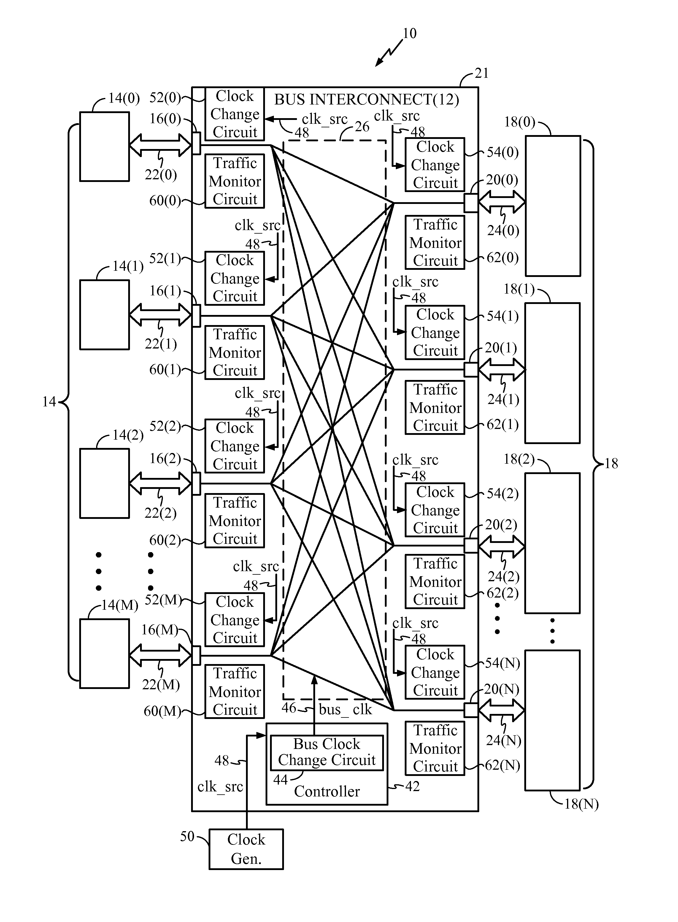
[0023]With reference now to the drawing figures, several exemplary embodiments of the present disclosure are described. The word “exemplary” is used herein to mean “serving as an example, instance, or illustration.” Any embodiment described herein as “exemplary” is not necessarily to be construed as preferred or advantageous over other embodiments.

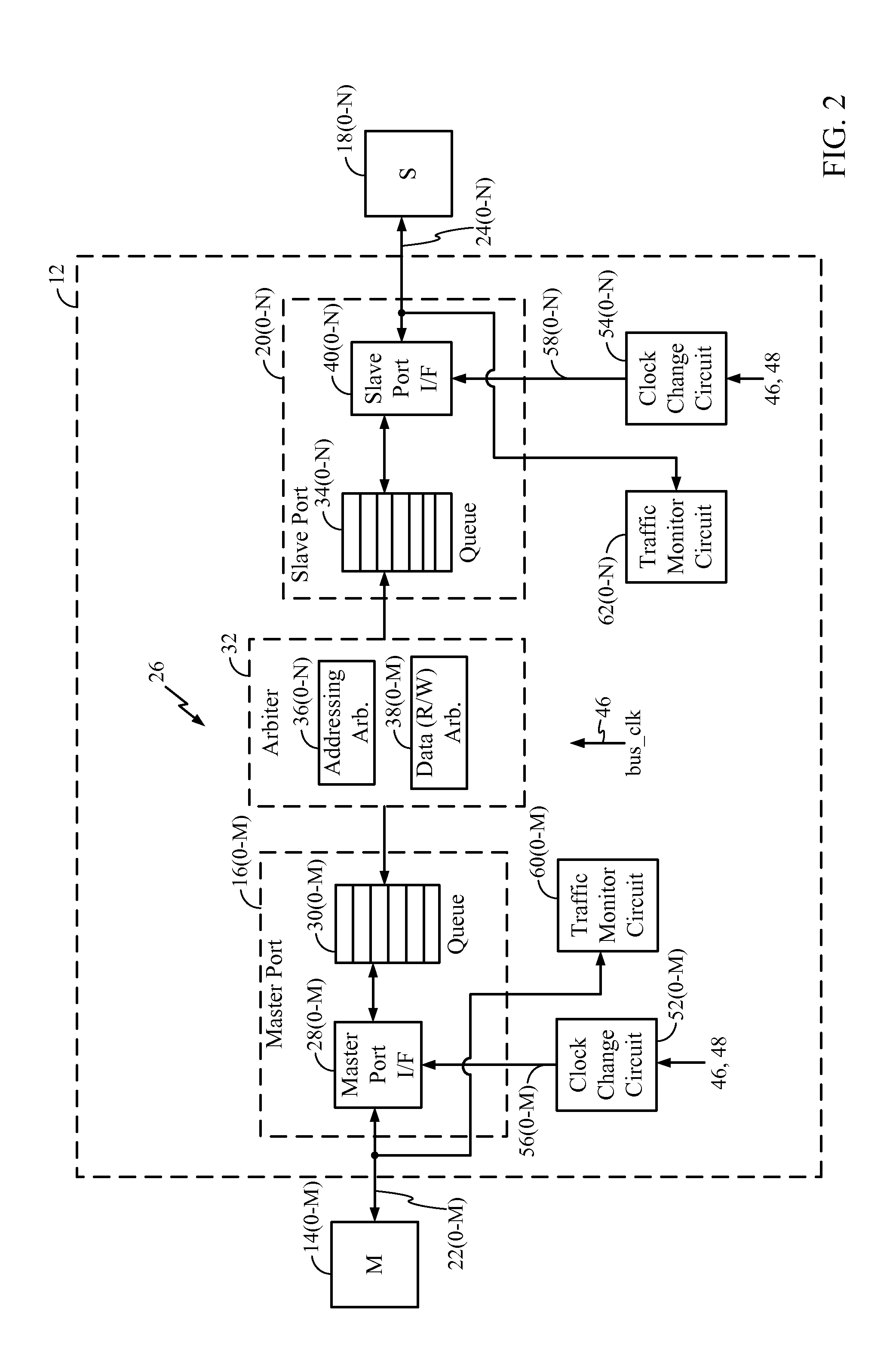
[0024]Embodiments disclosed in the detailed description include bus clock frequency scaling for bus interconnects, and related devices, systems, methods, and computer-readable mediums. The bus interconnect is configurable to allow one or more master devices, each connected to a master port among a plurality of master ports of the bus interconnect, to be communicatively connected to any of a plurality of slave devices each connected to a slave port of the bus interconnect. The master port(s) and slave port(s) may be configurable to operate at different frequencies to facilitate interconnection of a master device(s) operating one frequency t...


PUM


Abstract

Bus clock frequency scaling for a bus interconnect and related devices, systems, and methods are disclosed. In one embodiment, the bus interconnect comprises an interconnect network configurable to connect a master port(s) to a slave port(s). A bus interconnect clock signal clocks the interconnect network. The controller is configured to receive bandwidth information related to traffic communicated over the master port(s) and the slave port(s). The controller is further configured to scale (e.g., increase or decrease) the frequency of the bus interconnect clock signal if the bandwidth of the master port(s) and/or the slave port(s) meets respective bandwidth condition(s), and/or if the latency of the master port(s) meets a respective latency condition(s) for the master port(s). The master port(s) and/or slave port(s) can also be reconfigured in response to a change in frequency of the bus interconnect clock signal to optimize performance and conserve power.

Description

BACKGROUND[0001]I. Field of the Disclosure[0002]The technology of the disclosure relates to electronic bus interconnects for communicatively interfacing diverse electronic components together. As an example, the bus interconnects can be provided in system-on-a-chip (SOC) designs.[0003]II. Background[0004]Portable electronic devices, such as mobile phones, personal digital assistants (PDAs), and the like, are commonly manufactured using application specific integrated circuit (ASIC) designs. Developments in achieving high levels of silicon integration have allowed creation of complicated ASICs and field programmable gate array (FPGA) designs. These ASICs and FPGAs may be provided in a single chip to provide a system-on-a-chip (SOC). An SOC provides multiple functioning subsystems on a single semiconductor chip, such as for example, processors, multipliers, caches, and other electronic components. SOCs are particularly useful in portable electronic devices because of their integration...

Claims


Application Information

Patent Timeline
IPC IPC(8): G06F1/04G06F13/00
CPCG06F1/06G06F1/3209Y02B60/1217G06F13/4022Y02B60/1235G06F1/324Y02D10/00G06F13/40G06F1/04G06F1/32
Inventor HOFMANN, RICHARD GERARDGANASAN, JAYA PRAKASH SUBRAMANIAMLEWIS, BRANDON WAYNE
Owner QUALCOMM INC
Why Eureka
Try Eureka