Steam generation unit and steam cooking device using same

Inactive Publication Date: 2012-08-09
SHARP KK
View PDF5 Cites 13 Cited by
  • Summary
  • Abstract
  • Description
  • Claims
  • Application Information

AI Technical Summary

Benefits of technology

[0055]As apparent from the above description, the steam generation unit according to the invention includes the boiling-water intrusion preventing device provided on the steam supply path for supplying steam generated by the steam generation device to the steam-supplied chamber, so that upon occurrence of bumping in the steam generation device, boiling water can be prevented from intruding into the steam-supplied chamber. Therefore, occurrence of temperature specks in the steam-supplied chamber due to intrusion of the boiling water into the steam-supplied chamber can be prevented.
[0056]Further, since the boiling-water intrusion preventing device is provided on the steam supply path, the steam generation device can be provided in a simple structure including no protrusions or the like inside. Thus, a simple metal mold will do for cases in which the steam generation device is formed by metal die casting, so that leading to cost increases can be prevented. Further, since the steam generation device is in a simple structure, scale is less likely to accumulate inside, and moreover even accumulated scale is quite easy to remove.
[0057]Moreover, the steam cooking device according to the invention includes the steam generation unit capable of, upon occurrence of bumping in the steam generation device, preventing boiling water from intruding into the steam-supplied chamber. Therefore, upon occurrence of bumping in the steam generation device, boiling water can be prevented from intruding into the heating chamber as the steam-supplied chamber or the steam heating device. Thus, it can be prevented that the boiling water intrudes into the heating chamber and splashes onto the heating object to cause heating specks on the heating object. Otherwise, it can be prevented that the boiling water intrudes into the steam heating device and drops onto the bottom face of the steam heating device to cause temperature specks and, as a result, cause heating specks on the heating object in the heating chamber.
[0058]Further, the boiling water or water that has overflowed from the steam generation device can be prevented from splashing onto the steam heating heater of the on-state steam heating device and causing vapor explosions or the like.

Problems solved by technology

However, the conventional cooking device disclosed in Patent Literature 1 has the following problems.
Forming the container body having such a complex configuration by metal die casting with casting of the U-shaped steam heater is quite difficult because of complexity of the metal mold, leading to cost increases, problematically.
Therefore, scale is highly likely to accumulate in the steam generation container, and yet accumulated scale is quite hard to remove, problematically.
Thus, in the case of steamed cooking for puddings, chawan-mushi (custard-like egg and vegetable dishes steamed in a cup), or the like, heating with superheated steam of over 100° C. causes the dishes to be dried, resulting in a poor finished state, problematically.

Method used


Image

  • Steam generation unit and steam cooking device using same
  • Steam generation unit and steam cooking device using same
  • Steam generation unit and steam cooking device using same

Examples


first embodiment

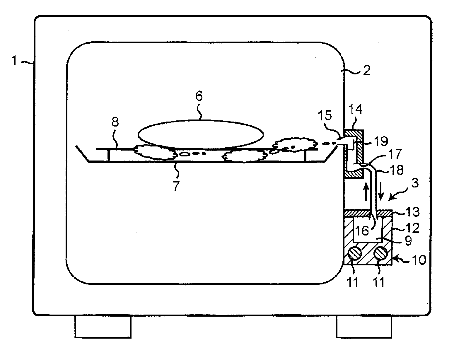
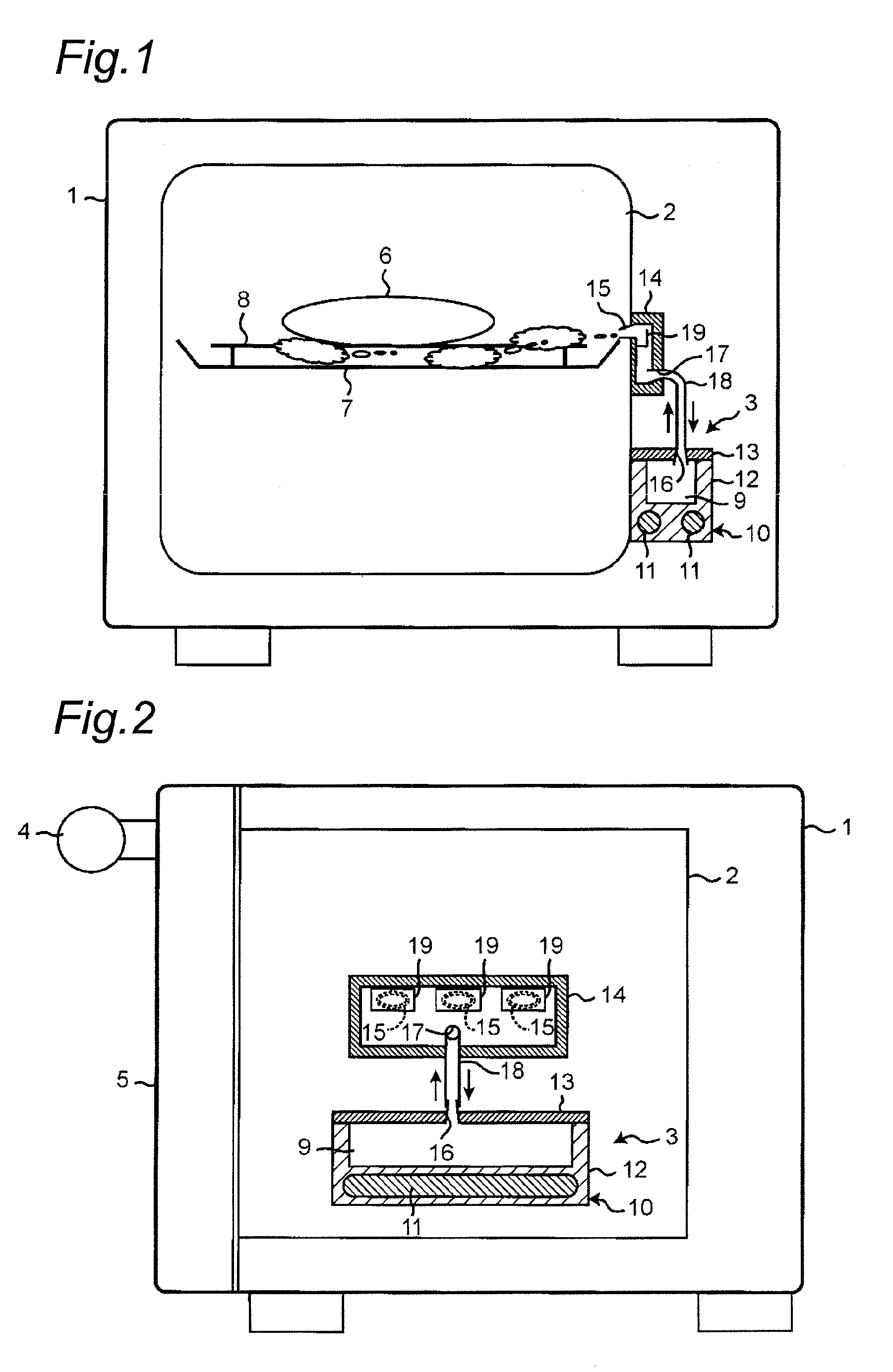
[0069]FIGS. 1 and 2 are schematic views showing a basic construction of a cooking device using a steam generation unit according to this embodiment. FIG. 1 is a longitudinal sectional view as viewed from its front side, and FIG. 2 is a longitudinal sectional view as viewed from a side-face side.

[0070]As shown in FIGS. 1 and 2, the cooking device includes a main casing 1, a heating chamber 2 for forming a steam-supplied space provided in the main casing 1, and a steam generation device 3 for generating steam.

[0071]The heating chamber 2 has an opening on its front side, and its side plates, bottom plate and top plate are formed of stainless steel plates. By opening and closing the opening with a door 5 equipped with a handle 4, a user is allowed to put a heating object (food) 6 into and out of the heating chamber 2 through the opening. Around the heating chamber 2, a heat insulating material (not shown) is placed to thermally insulate inside of the heating chamber 2 from its outside.

[...

second embodiment

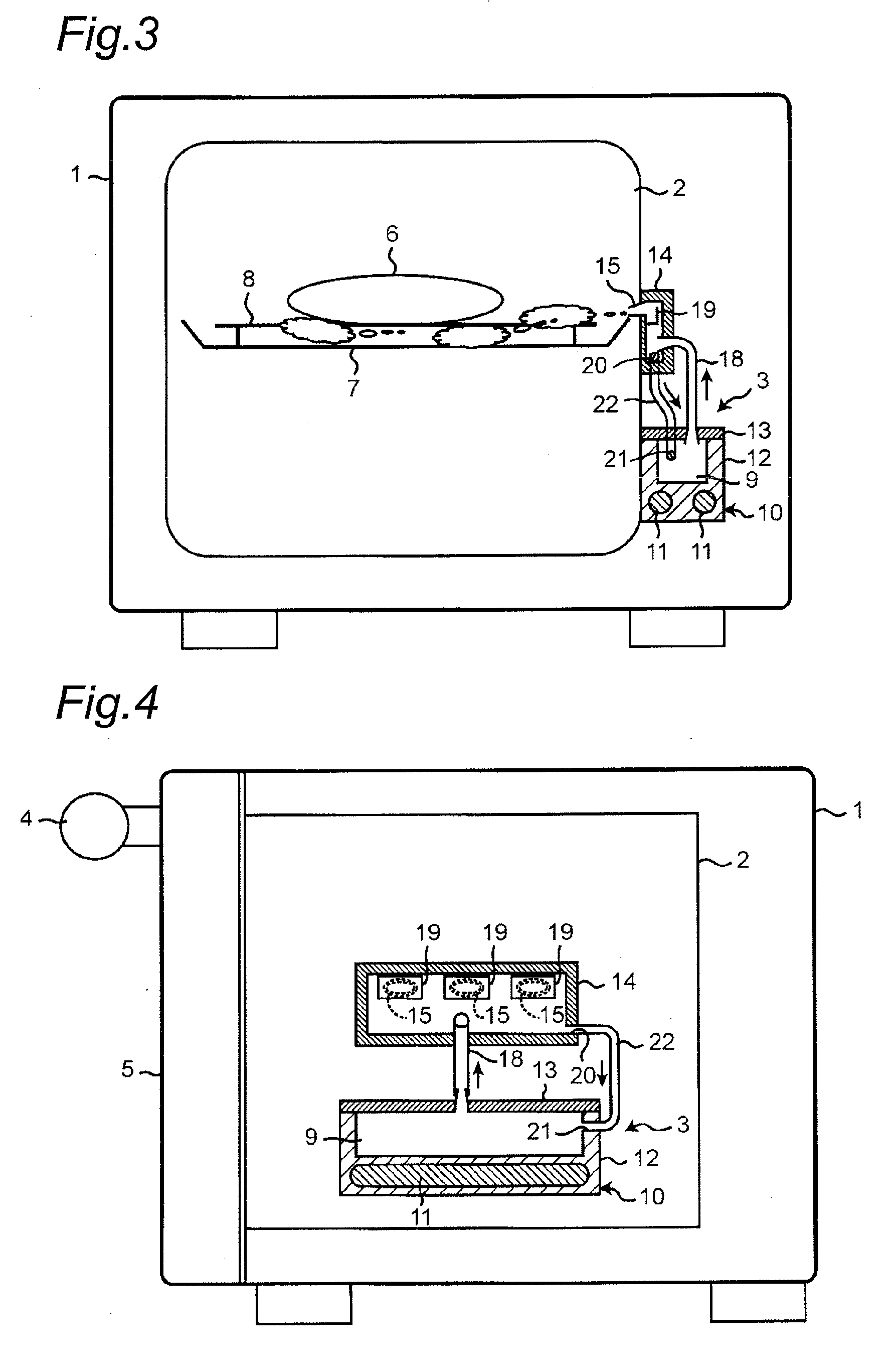
[0099]In the first embodiment described above, the steam generation device 3 is placed on a side wall of the heating chamber 2 so that saturated steam generated by the steam generation device 3 is jetted out into the heating chamber 2. In contrast to this, there has been provided a cooking device in which a steam heating device with a steam-heating heater contained therein is placed on a heating chamber so that saturated steam generated by the steam generation section placed outside the heating chamber is jetted into the heating chamber via the steam heating device. In this case, when the steam-heating heater is turned on, superheated steam heated to an superheated state of 100° C. or higher is jetted into the heating chamber. When the steam-heating heater is turned off, saturated steam is jetted as it is into the heating chamber. This embodiment relates to a cooking device in which saturated steam generated by the steam generation section is jetted into the heating chamber via the ...

third embodiment

[0108]This embodiment also relates to a cooking device in which saturated steam generated by a steam generation section is jetted into a heating chamber via a steam heating device as in the second embodiment.

[0109]FIG. 8 is a view showing main part of a cooking device using a steam generation unit according to this embodiment. In FIG. 8, the main casing has been removed.

[0110]In the steam generation unit of this embodiment, the steam generation device 31 and the steam heating device 32 are positioned generally equal in vertical position to each other. Then, the steam generation unit of this embodiment differs from the steam generation unit of the second embodiment in that the steam generation device 31 and the steam heating device 32 are connected to each other by a steam supply pipe 44 extending so as to go once upward from the steam generation device 31 side toward the steam heating device 32 side and then go downward. Hereinbelow, the same component members as in the steam genera...


PUM


Abstract

A steam generation device is placed at a lower portion of a side wall of a heating chamber. A steam jet-out part is placed upper than the steam generation device of the side wall of the heating chamber with a distance from the steam generation device. Thus, even if bumping has occurred within a water storage part of the steam generation device, causing boiling water to rush out from a steam supply port into a steam supply pipe, the boiling water is prevented from intruding into a steam jet-out part.

Description

TECHNICAL FIELD[0001]The present invention relates to a steam generation unit, and a steam cooking device using the same, for supplying steam to a steam-supplied room.BACKGROUND ART[0002]A conventional cooking device for performing heat cooking with steam generated by a steam generation device is disclosed in JP 2008-164284 A (Patent Literature 1). This cooking device includes a magnetron and a heater as heating means so as to enable to fulfill microwave oven cooking and oven cooking. Further, a steam generation container is placed in a side portion of a heating chamber.[0003]The steam generation container is composed of a container body formed of a recess portion having an opening and a container cover for closing the opening of the container body. The container cover is screwed to the container body, by which a steam generation chamber is defined. A U-shaped steam heater is cast inside the container body. Also a water supply port is provided in the container body. On the other han...

Claims


Application Information

Patent Timeline
IPC IPC(8): A47J27/04
CPCF22B1/284A21B3/04A47J27/04F24C15/327
Inventor SEGUCHI, YOUHEIUEDA, SHINYAUTSUMI, TAKASHI
Owner SHARP KK
Why Eureka
Try Eureka