This helps you quickly interpret patents by identifying the three key elements:
Problems solved by technology
Method used
Benefits of technology
Benefits of technology
The present invention relates to a refrigeration system with an improved control unit cooling portion. By using refrigerant in a liquid-rich state, the control unit can be efficiently cooled, resulting in increased heat conduction efficiency and improved compression efficiency of the compressor. Additionally, a dew-point temperature sensor and an opening degree adjustment portion can be used to prevent dew condensation on the control unit. These technical effects allow for a smaller outdoor unit volume and improved cooling performance.
Problems solved by technology
Therefore, there is a problem in that, at low differential pressure when the refrigeration cycles are activated, a flow rate of a refrigerant to cool the control unit is not secured in the control unit cooling portion and thus the control unit is excessively heated.
In addition, in a conventional structure of providing the control unit cooling portion in the main refrigerant circuit, there is a problem in that the control unit is insufficiently cooled when a flow rate of the refrigerant within the main refrigerant circuit needs to be reduced due to oil foaming or the like in which lubricant is brought to an indoor unit in quantity.
Thus, it is undesirable to install the control unit cooling portion to the main refrigerant circuit configuring a series of refrigeration cycles so as to cool the control unit.
However, in the technique disclosed in Japanese Patent Publication No. 2010-2112, since the inverter device, which is a type of control unit, is insufficiently cooled, desired cooling efficiency may not be obtained.
This is because the refrigerant introduced into the inverter cooling portion may not be maintained to a state suitable for cooling in the configuration of the refrigeration device in Japanese Patent Publication No. 2010-2112.
Method used
Image
Click on the blue label to locate the original text in one second.
Reading with bidirectional positioning of images and text.
Examples
first embodiment
[0027]Hereinafter, an air conditioner 1 according to a first embodiment of the present disclosure will be described with reference to FIGS. 1 to 3.
[0028][Configuration of Air Conditioner 1]
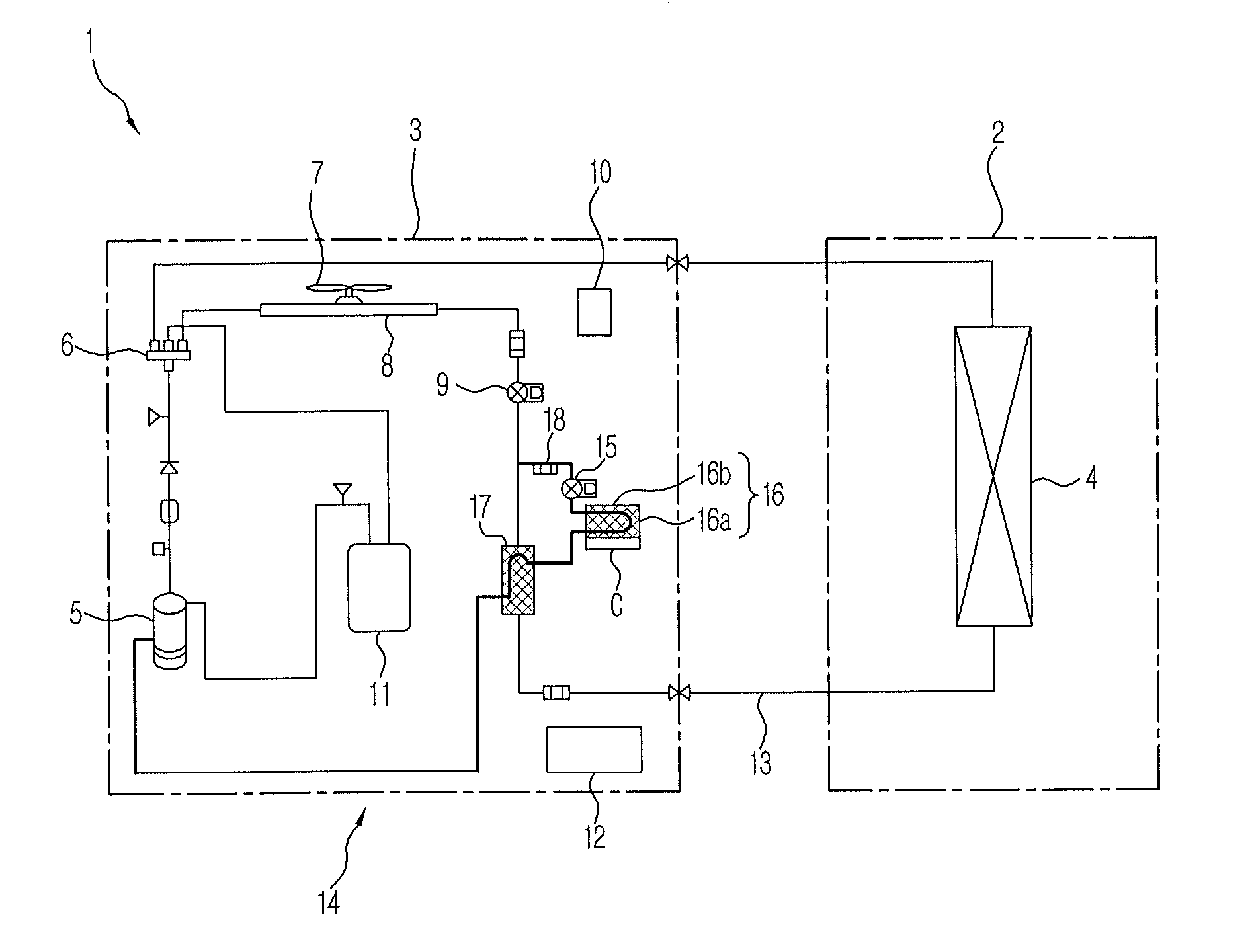
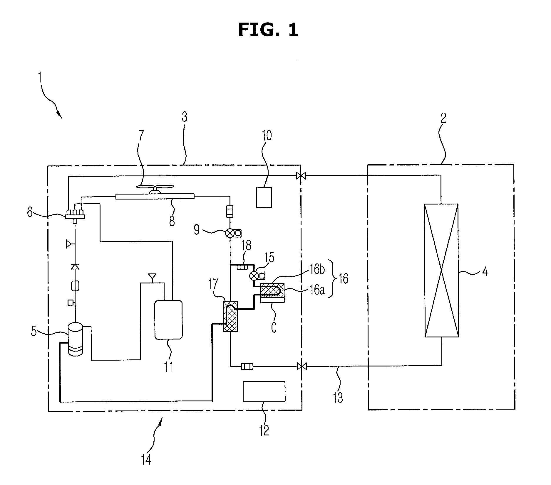
[0029]FIG. 1 illustrates a configuration example of an air conditioner 1 according to a first embodiment of the present disclosure. The air conditioner 1 is an air conditioner 1 including an inverter circuit cooling portion (a control unit cooling portion) 16 capable of cooling an inverter circuit C (a control unit) to inverter-control a compressor 5 using a refrigerant, and includes an indoor unit 2 and an outdoor unit 3 as shown in FIG. 1.
[0030]The indoor unit 2 includes an indoor heat exchanger 4, a room temperature sensor (not shown) capable of detecting a room temperature in a room, a remote (not shown), and the like.
[0031]The outdoor unit 3 includes a compressor 5, a four-way valve 6, an outdoor fan 7, an outdoor heat exchanger 8, an expansion valve 9, an outdoor air temperature sensor 10 ca...
second embodiment
[0051]Hereinafter, an air conditioner 1 according to a second embodiment of the present disclosure will be described with reference to FIGS. 4 and 5. In addition, components similar to those described in the first embodiment are designated by similar reference numerals, and no detailed description with respect to the similar components will be given. The second embodiment differs from the first embodiment in that the injection circuit 14 includes a throttlepipe 19.
[0052][Configuration of Injection Circuit 14]
[0053]As shown in FIG. 4, the injection circuit 14 includes the injection pipe 18 (indicated by a thick line in FIG. 4) configured such that the refrigerant diverges between the outdoor heat exchanger 8 and indoor heat exchanger 4 and returns to the compressor 5. The injection circuit 14 includes the injection decompression valve 15, the inverter circuit cooling portion 16, the sub-cooler evaporation portion 17, and the throttlepipe 19 which are provided on the injection pipe ...
third embodiment
[0060]Hereinafter, an air conditioner 1 according to a third embodiment of the present disclosure will be described with reference to FIGS. 6 and 7. In addition, components similar to those described in the first embodiment are designated by similar reference numerals, and no detailed description with respect to the similar components will be given. The third embodiment differs from the first embodiment in that the control portion 12 includes an inverter circuit temperature detection portion (control unit temperature detection portion) 20, a dew-point temperature calculation portion 21, and an opening degree adjustment portion 22.
[0061][Configuration of Control Portion 12]
[0062]FIG. 6 a block diagram illustrating a configuration of the control portion 12 according to the third embodiment of the present disclosure. As shown in FIG. 6, the control portion 12 includes the inverter circuit temperature detection portion 20, the dew-point temperature calculation portion 21, and the openin...
PUM
Abstract
An air conditioner includes a main refrigerant circuit where refrigerant flows in order of a compressor, outdoor heat exchanger, expansion valve, and indoor heat exchanger. An injection circuit is configured such that the refrigerant diverges between the outdoor heat exchanger and indoor heat exchanger in the main refrigerant circuit and returns to the compressor having a pressure between a suction pressure of compressor and a discharge pressure of compressor. The injection circuit includes an injection decompression valve reducing a pressure of the refrigerant, a control unit cooling portion cooling a control unit to control the compressor using the refrigerant, and a sub-cooler evaporation portion provided at a downstream side of the injection decompression valve such that heat exchange of the refrigerant is performed in the sub-cooler evaporation portion, and the control unit cooling portion is provided between the injection decompression valve and the sub-cooler evaporation portion in the injection circuit.
Description
CROSS-REFERENCE TO RELATED APPLICATIONS[0001]This application claims the benefit of Japanese Patent Application No. 2012-254434, filed on Nov. 20, 2012 in the Japanese Patent Office, the disclosure of which is incorporated herein by reference.BACKGROUND[0002]1. Field[0003]Embodiments of the present disclosure relate to an air conditioner having a control unit cooling portion which cools a control unit to control a compressor using a refrigerant.[0004]2. Description of the Related Art[0005]In a conventional refrigeration device, a control unit cooling portion which cools a control unit to control a compressor using a refrigerant is installed to a main refrigerant circuit configuring a series of refrigeration cycles. Therefore, there is a problem in that, at low differential pressure when the refrigeration cycles are activated, a flow rate of a refrigerant to cool the control unit is not secured in the control unit cooling portion and thus the control unit is excessively heated.[0006]...
Claims
Application Information
Patent Timeline
Application Date:The date an application was filed.
Publication Date:The date a patent or application was officially published.
First Publication Date:The earliest publication date of a patent with the same application number.
Issue Date:Publication date of the patent grant document.
PCT Entry Date:The Entry date of PCT National Phase.
Estimated Expiry Date:The statutory expiry date of a patent right according to the Patent Law, and it is the longest term of protection that the patent right can achieve without the termination of the patent right due to other reasons(Term extension factor has been taken into account ).
Invalid Date:Actual expiry date is based on effective date or publication date of legal transaction data of invalid patent.

