Metal-sealing material-feedthrough and utilization of the metal-sealing material feedthrough with an airbag, a belt tensioning device, and an ignition device

a technology of metal sealing material and feedthrough, which is applied in the direction of engine sealing, pressure gas generation, weapons components, etc., can solve the problems of uneconomic fabrication, material intensive and expensive construction types, and the limit of punching fabrication, so as to reduce the support surface of sealing material slugs, save materials, and save energy.

Active Publication Date: 2012-08-09
SCHOTT AG
View PDF6 Cites 7 Cited by
  • Summary
  • Abstract
  • Description
  • Claims
  • Application Information

AI Technical Summary

Benefits of technology

[0018]For applications in ignition devices for airbags base bodies having a thickness of between 1 mm and 5 mm, preferably 1.5 mm and 3.5 mm, especially preferably 1.8 mm to 3.0 mm, more especially preferably 2.0 mm to 2.6 mm are used. Even with consistently sized metal pins this represents a considerable saving in materials due to the smaller dimensions compared to the pivoted component which has thicknesses for example, of 3.2 mm to 5 mm, as well as providing an energy saving manufacturing process. In addition, the reduction in the support surface for the sealing material slug which is inherent with the reduction in the thickness can be compensated for with regard to its function, by simple measures which require almost no additional expenditure.
[0019]A base body with a thickness of between 1 mm and 5 mm, preferably 1.5 mm and 3.5 mm, especially preferably 1.8 mm to 3.0 mm, more especially preferably 2.0 mm to 2.6 mm, can be deformed under compression. The deformation under compression prevents a relative movement of the sealing material in a direction toward a back side of the base body of the metal sealing material feedthrough. This is due to the effect that due to the deformation a local bending stress at the front side and / or the back side of the base plate occurs. By the bending stress especially at the front side of the base plate the fixing material, especially the glass slug, within the feedthrough opening is fixed. In other words, the bending stress provides the feedthrough opening and the glass slug within the feedthrough opening with an additional force which is directed in general in parallel to the surface of the base body. This additional force increases the holding force of the glass slug within the feedthrough opening. This mechanism can be understood as if the diameter of the feedthrough opening would be locally reduced during the bending if no glass slug would be present in the feedthrough opening. In the presence of the glass slug, the diamterer reduction is prevented, but the additional force additionally fixes the glass slug in the feedthrough opening. This inventive measure provides for a high hydrostatic pressure which must be applied in order to eject the fixing material, especially the glass slug. The hydrostatic pressure necessary to eject the glass slug can be even more increased in case of a conical feedthrough opening, with a smaller diameter at the back side than at the front side. This is due to the fact that in case of a conical shaped feedthrough opening a bending stress occurs at the front side as well as at the back side.

Problems solved by technology

One fundamental problem in this embodiment is that this type of construction is material intensive and expensive.
There are no restrictions regarding the material choices for the base body so that, depending upon design, especially when constructed as a pivoted component, the already mentioned disadvantages also occur, which only intensify through the additional necessary inclusion of the required ways for the increase of the tensile force, extraction force, and / or ejection force.
However, fabrication by way of punching is subject to limits with a view to individual material related parameters exceeding of which would render the fabrication uneconomical and which would also have a negative effect upon the available ejection force.

Method used


Image

  • Metal-sealing material-feedthrough and utilization of the metal-sealing material feedthrough with an airbag, a belt tensioning device, and an ignition device
  • Metal-sealing material-feedthrough and utilization of the metal-sealing material feedthrough with an airbag, a belt tensioning device, and an ignition device
  • Metal-sealing material-feedthrough and utilization of the metal-sealing material feedthrough with an airbag, a belt tensioning device, and an ignition device

Examples


Embodiment Construction

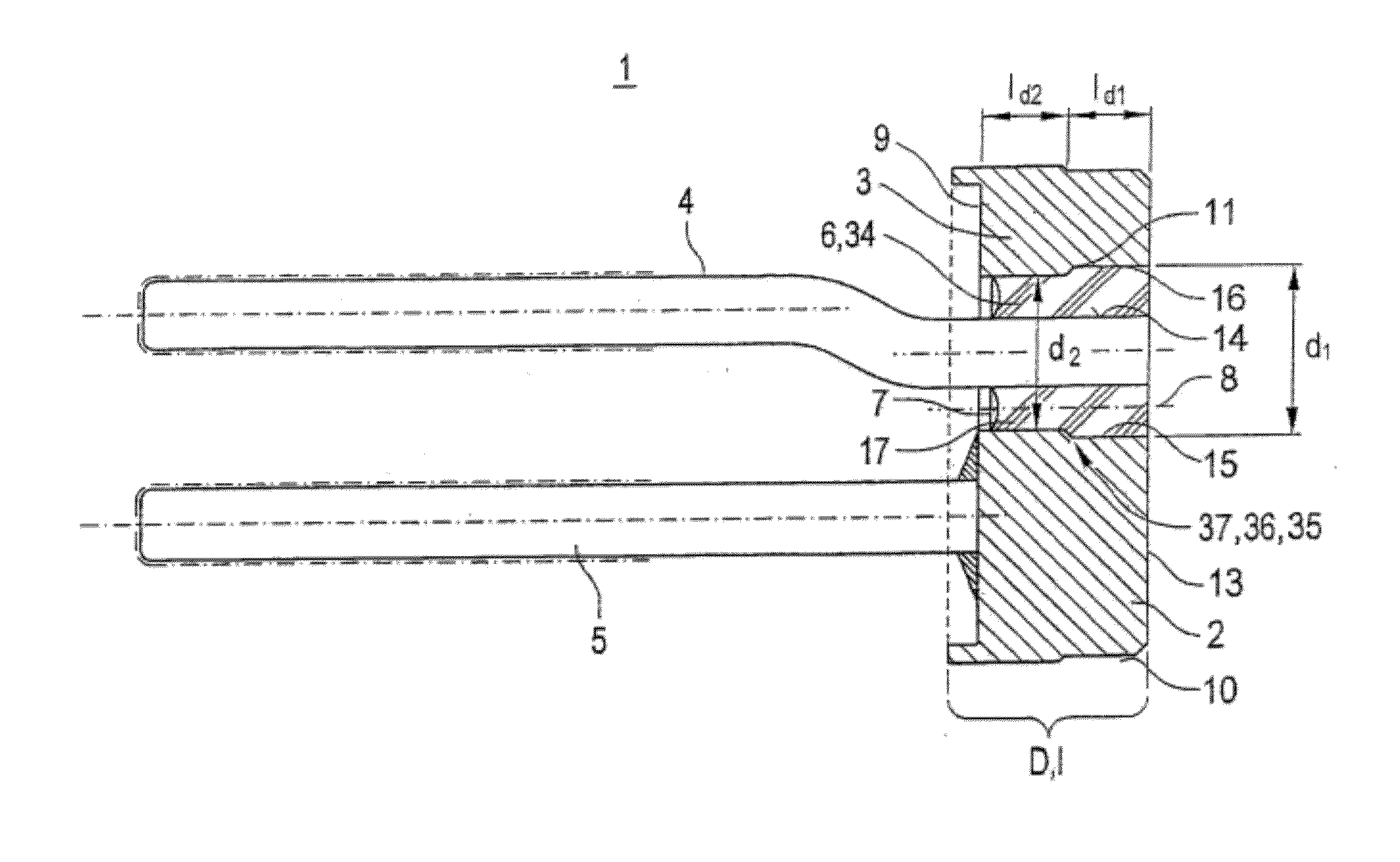
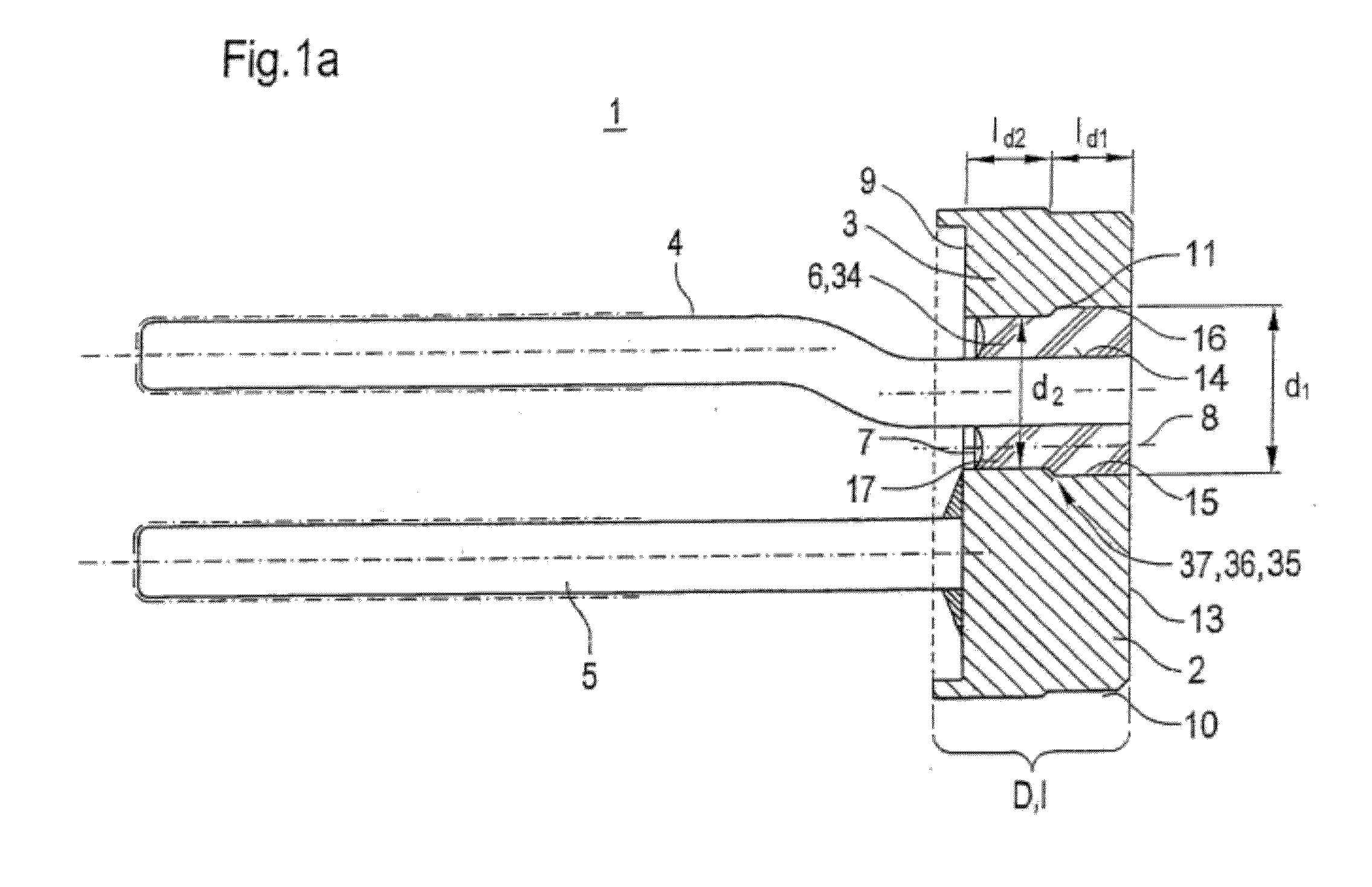
[0058]Referring now to the drawings, and more particularly to FIG. 1a, there is shown, with the assistance of an axial section, a first design of an inventively constructed metal-sealing material-feedthrough 1, which can be used as an igniter or an ignition device of an airbag. This includes a base body 3 forming a metal collar 2 with which two parallel metal pins 4 and 5 are electrically connected. The two metal pins 4 and 5 are located parallel to each other. One of said metal pins functions as a conductor while the second one is grounded. In the illustrated example the first metal pin 4 functions as conductor and the metal pin 5 as grounding pin. At least one of the metal pins, especially the one metal pin 4 functioning as conductor is inserted through the base body 3. In this context the metal pin 4 is sealed over a section of its length 1 in sealing material 34, especially in a glass slug 6 which is cooled from a molten glass mass. In the illustrated example the metal pin 4 pro...


PUM

PropertyMeasurementUnit
thicknessaaaaaaaaaa
thicknessaaaaaaaaaa
thicknessaaaaaaaaaa

Abstract

A metal-sealing material-feedthrough for igniters includes: a base body including a feedthrough opening, a front side, and a back side, the base body configured such that a ratio of a thickness of the base body to a maximum dimension of the feedthrough opening vertical to an axis direction of the feedthrough opening is in a range of approximately 0.5 to 2.5, the base body having a thickness between 1.5 mm and 3.5 mm; a sealing material; and a metal pin which is located in the feedthrough opening, the thickness being such that the base body is deformed under compression, the deformation adding an additional force to the sealing material such that the metal-sealing material-feedthrough is configured for avoiding a relative movement of the sealing material between the front side and the back side in a direction toward the back side relative to an inside circumference of the feedthrough opening.

Description

CROSS REFERENCE TO RELATED APPLICATIONS[0001]This is a continuation-in-part of U.S. patent application Ser. No. 11 / 627,173, entitled “METAL-SEALING MATERIAL-FEEDTHROUGH AND UTILIZATION OF THE METAL-SEALING MATERIAL FEEDTHROUGH WITH AN AIRBAG, A BELT TENSIONING DEVICE, AND AN IGNITION DEVICE”, filed Jan. 25, 2007, which is incorporated herein by reference.BACKGROUND OF THE INVENTION[0002]1. Field of the Invention[0003]The current invention relates to a metal-sealing material-feedthrough. It further relates to usage as well as to a gas generator, airbag and belt tensioning device including an ignition device, comprehensively a metal-sealing material-feedthrough.[0004]2. Description of the Related Art[0005]Metal-sealing material feedthroughs are already known in various forms from the current state of the art. They are understood to be vacuum-tight seals of sealing materials, especially glass or synthetics to metal seals. In this type or arrangement the metals act as electrical conduct...

Claims


Application Information

Patent Timeline
Patent Type & Authority Applications(United States)
IPC IPC(8): F16J15/02C06D5/00
CPCF42B3/198F42B3/103
Inventor FINK, THOMAS
Owner SCHOTT AG
Why Eureka
Try Eureka