
Dielectric structure that withstands compression

Inactive Publication Date: 2012-08-09
NEXANS
View PDF3 Cites 3 Cited by
  • Summary
  • Abstract
  • Description
  • Claims
  • Application Information

AI Technical Summary

Benefits of technology

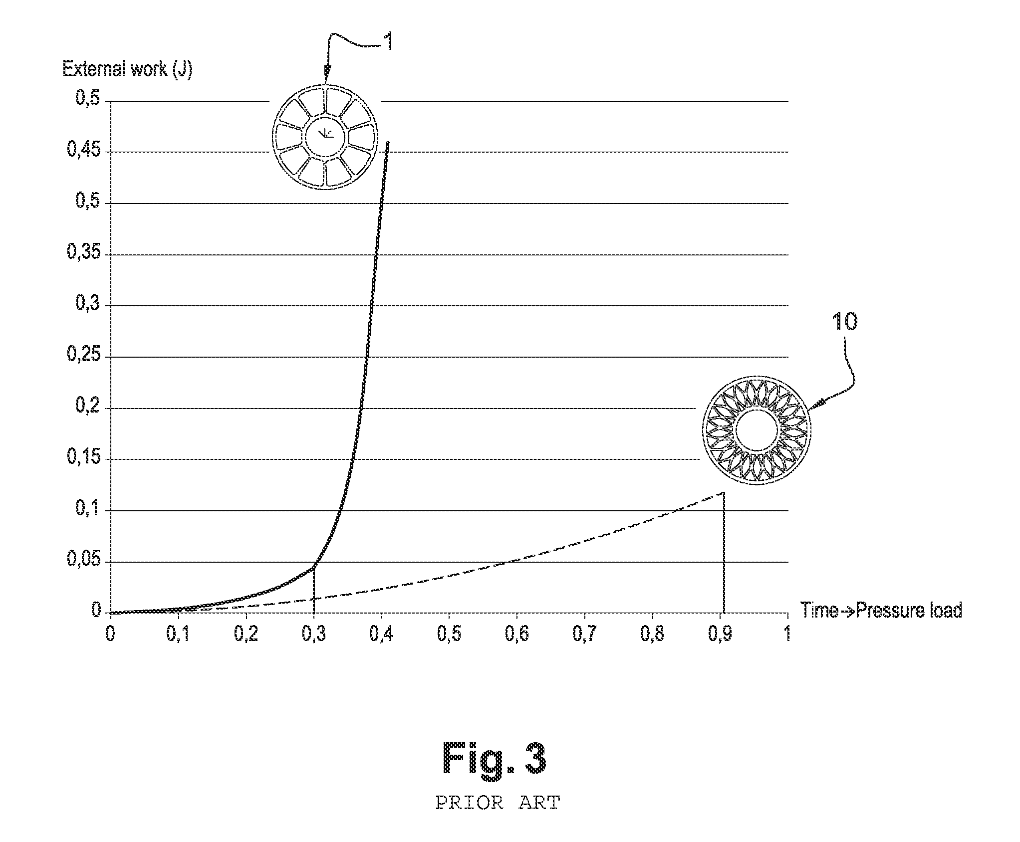
[0006]Dielectric structures of the invention present a special shape giving them excellent mechanical strength, in particular against, flattening, as might occur, for example, as a result of compression type external stress. Furthermore, the structures can be fabricated easily and quickly, and any defects that might arise during their fabrication are unlikely to undermine the mechanical strength of said structures, with this being because of their special shape, which is capable of accommodating a certain amount of inaccuracy in fabrication.
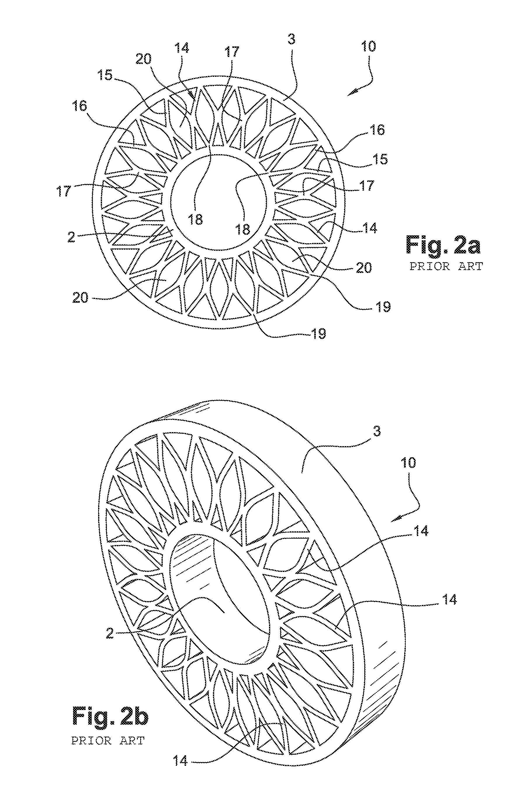
[0010]Preferably, the space left between two successive spacers is lozenge-shaped, with its two vertices that are interconnected by an axis tangential to the structure being rounded. To be more precise, each spacer has an X-shaped section, and putting into contact two spacers that are situated at the same height serves, to reveal an “inter-spacer” gap that is lozenge-shaped. The two rounded vertices come from the curved shape of the walls of the spacers. The fact of eliminating two sharp vertices from the lozenge serves to eliminate two rupture zones that might lead to the structure being flattened when subjected to compression.
[0013]In another preferred embodiment of a dielectric structure of the invention, the two walls of a given spacer possess two intersection zones, serving to strengthen their ends.
[0017]Dielectric structures of the invention for electric cables or wires present the advantage of possessing mechanical strength properties of withstanding compression that are greatly increased compared with already-existing structures, merely by a simple change of shape, they do not require any complex fabrication techniques, and they do not require any reinforcing parts to be added. Furthermore, this modification enables the general outlines of the structure to be preserved, thus enabling is to replace already-existing structures, without requiring any new arrangements or assembly readjustments.

Problems solved by technology

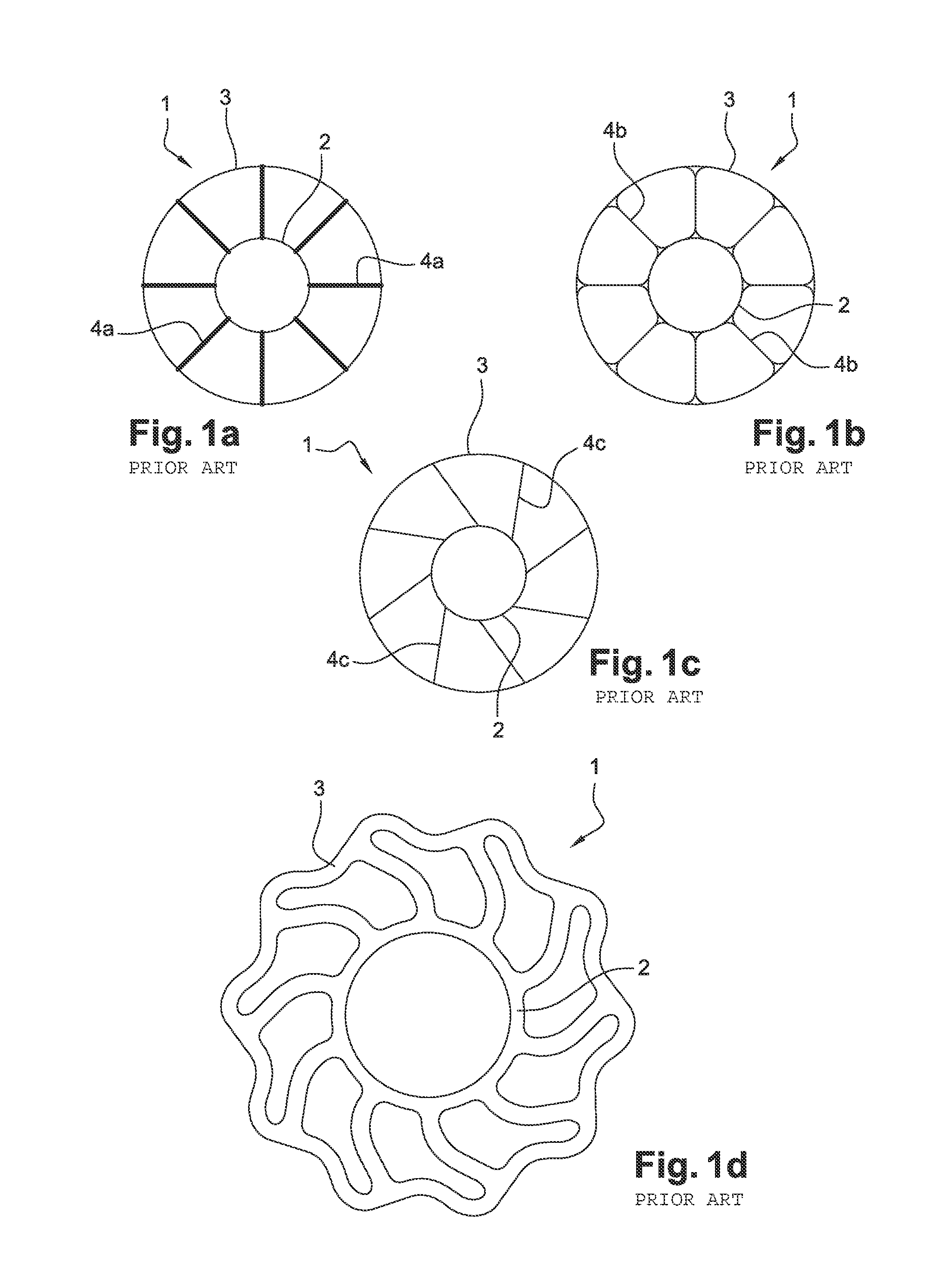
Apart from the fact of providing a level of strength that is only just satisfactory, without any safety margin, such “daisy” structures have the additional drawback of repeatedly presenting fabrication defects that are inherent to the extrusion method by which they are made.
Unfortunately, the use of Freon as a foaming gas is no longer authorized, so such foaming structures cannot constitute satisfactory solutions to the problem posed.
Furthermore, the structures can be fabricated easily and quickly, and any defects that might arise during their fabrication are unlikely to undermine the mechanical strength of said structures, with this being because of their special shape, which is capable of accommodating a certain amount of inaccuracy in fabrication.
Nevertheless, the fact that the intersection zone of the two walls corresponds to their central portions being put into contact does not mean that the contact takes place rigorously and accurately in their geometrical centers.

Method used


Image

  • Dielectric structure that withstands compression
  • Dielectric structure that withstands compression
  • Dielectric structure that withstands compression

Examples


Embodiment Construction

[0026]With reference to FIG. 2a, a dielectric structure 10 of the invention presents an inner hollow cylindrical body 2 and an outer hollow cylindrical body 3 that are connected together by a plurality of identical spacers 14. Each spacer 14 is constituted by a. first curved. wall 15 and by a second curved wall 16 that is curved in the opposite direction relative to a radial plane interconnecting the two bodies 2 and 3, and separating said walls 15 and 16, said walls 15 and 16 being secured to each other substantially via their central portions. This zone 17 of contact between the two walls 15 and 16 of a spacer 14 need not be accurately central, and may vary around a central position with a certain amount of tolerance. For this configuration, the essential point is than the section of each spacer 14 in a cross-section relative to a longitudinal, axis of revolution of the dialectic structure 10 of the invention is generally X-shaped. Each wall15, 16 of a spacer 14 presents a first e...


PUM


Abstract

A dielectric structure (10) for an electric wire or cable, presenting an inner hollow cylindrical body (2) and an outer hollow cylindrical body (3), said bodies (2, 3) being coaxial and being connected together by a plurality of spacers (4a, 4b, 4c, 14). The main characteristic of a dielectric structure is that each spacer (14) is constituted by a first curved wall (15) and by a second curved wail (16) that is curved in the opposite direction relative to a radial plane interconnecting the two bodies (2, 3), the walls (15, 16) having at least one intersection zone (17), two successive spacers (14) being in contact with each other.

Description

RELATED APPLICATION[0001]This application claims the benefit of priority from French Patent Application No. 11 50884, filed on Feb. 3, 2011, the entirety of which is incorporated by reference.BACKGROUND[0002]1. Field Of The Invention[0003]The invention relates to a dielectric structure for an electric wire or cable. Electric cables or wires are generally surrounded by a dielectric structure that serves to isolate them from any external elements. In order to preserve said electric cables or wires from any external and accidental mechanical stress that might lead to them being damaged by compression or flattening, such dielectric structures are dimensioned so as to present good mechanical strength. Thus, such dielectric structures absorb, in part or in full, the forces that arise during such unwanted stresses, by deforming to a greater or lesser extent.[0004]2. Description of Related Art[0005]Existing dielectric structures the present acceptable compression strength are constituted by...

Claims


Application Information

Patent Timeline
IPC IPC(8): F16L55/00
CPCH01B7/0233H01B11/02H01B7/185
Inventor RYBSKI, PATRICKTRUONG, BRUNOVEAUX, MICHAELCLOUET, PASCAL
Owner NEXANS
Learn More