
Power Source For Starting Engines of Vehicles and the Like

Inactive Publication Date: 2012-08-09
OMNITEK PARTNERS LLC
View PDF3 Cites 11 Cited by
  • Summary
  • Abstract
  • Description
  • Claims
  • Application Information

AI Technical Summary

Benefits of technology

[0007]A need therefore exists for power sources for starting car or the like engines when the vehicle or the like battery cannot deliver sufficient current to the starter motor to start the engine that is convenient to use; its reliability is not dependent on regular testing of the device for proper ope

Problems solved by technology

A motor vehicle storage battery frequently falls into a state of discharge such that it cannot deliver sufficient current to the starter motor.
This is often due to lights or other accessories being accidently left on.
Also, defective vehicle charging systems or the age of the battery can result in the same problem.
The disadvantages of such power sources for starting a car or the like engines when the vehicle or the like battery cannot deliver sufficient current to the starter motor to start the engine include firstly the need to ensure that the rechargeable battery is always charged—which is a problem since most users do not spend the time to check the power source on a regular basis; secondly the fact that even rechargeable batteries have limited life and may not be fully operational when needed after a few years, i.e., have a relatively short life; thirdly, the amount of power that the power source can provide deteriorates over time; and fourthly, the power sources are usually relatively large and in general can suffer from corrosion and leaks over times. In addition, all currently available rechargeable batteries use hazardous materials and must be disposed properly and in general pose to pollute the environment.

Method used


Image

  • Power Source For Starting Engines of Vehicles and the Like
  • Power Source For Starting Engines of Vehicles and the Like
  • Power Source For Starting Engines of Vehicles and the Like

Examples


embodiment 50

[0063]In the embodiment 50 of FIG. 7 and for the aforementioned type of initiators used to activate the thermal battery, a safety pin or cap or switch (not shown) can be used to prevent unintended activation of the thermal battery. Such devices for preventing unintended actuation of a switch or caps that have to be removed or displaced to access activation switches or levers are well known in the art and may be used for this purpose.

[0064]In another embodiment, an aforementioned piezoelectric type of initiator (hereinafter referred to as “piezo initiator”) is used to activate the thermal battery by generating sparks upon actuation. Piezoelectric ignition is a type of ignition that is commonly used in gas stoves, portable camping stoves, gas grills and some other types of lighters. It consists of a small, spring-loaded hammer which, when a button is pressed, hits a crystal of piezoelectric element (PZT) or quartz crystal. This sudden forceful deformation (impact) produces a high volt...

embodiment 60

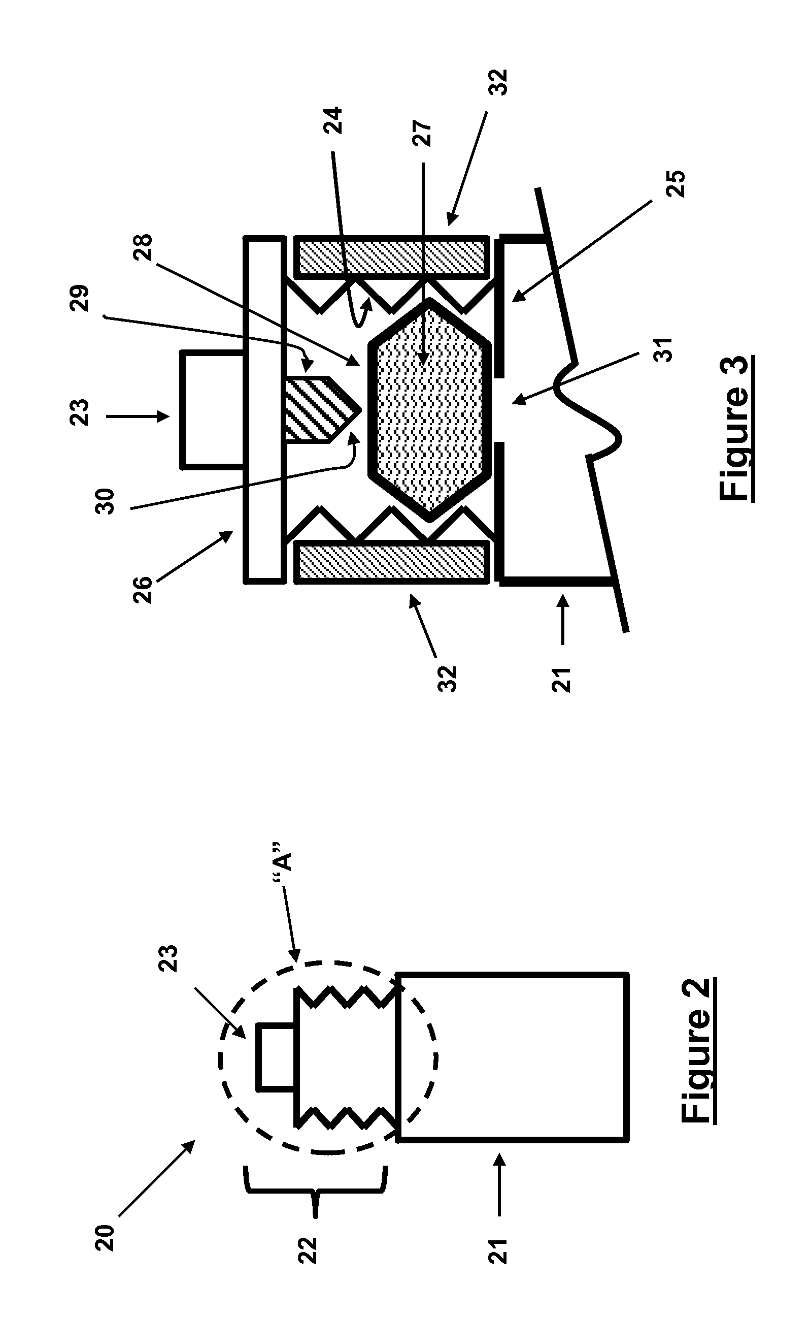
[0065]In this embodiment 60, a “piezo initiator”61 is attached to the thermal battery cell 62 as shown in the schematic of FIG. 9. For the sake of simplicity, a button type “piezo igniter” (button indicated by numeral 63) is shown in the schematic of FIG. 9. The schematic of the cross-section of the view “C” (FIG. 9) shown in FIG. 10. In FIG. 10, the “piezo initiator” portion 61 is shown to consist of a chamber 64, in which certain pyrotechnic material with or without certain intermediate and more easily ignited material such as the so-called heat papers 65 is provided.

[0066]To activate the thermal battery 60, the user would press on the “piezo igniter” button 63, thereby causing the igniter to generate an electrical discharge 66, which would in turn ignite the pyrotechnic material 65. The flame and sparks generated by the pyrotechnic material 65 would then enter the thermal battery cell 62 through the provided hole 67, and ignite the thermal battery heat pallets. As previously indi...

embodiment 70

[0067]In another embodiment 70, which is shown schematically in FIG. 11, employs an impact based initiator 71 to initiate the thermal battery. The basic mechanism of operation of this initiator is similar to the aforementioned “inertial igniters”, with the difference being that the impact is achieved by a spring that is preloaded and then released by pushing a button (similar to the aforementioned “piezo igniter”), pulling a lever or handle (to preload a spring in tension or compression and then release it upon further pulling of the lever or handle), or rotation of a lever (to similarly preload a spring in either tension or compression and then release it upon further rotation of the lever), or the like. A “hammer” or “striker mass” is attached to the releasing end of the spring and is thereby released upon the release of the spring. The “hammer” or “striker mass” would then strike an “anvil” (a base striking element). One part or two part pyrotechnic materials are at the point of ...


PUM


Abstract

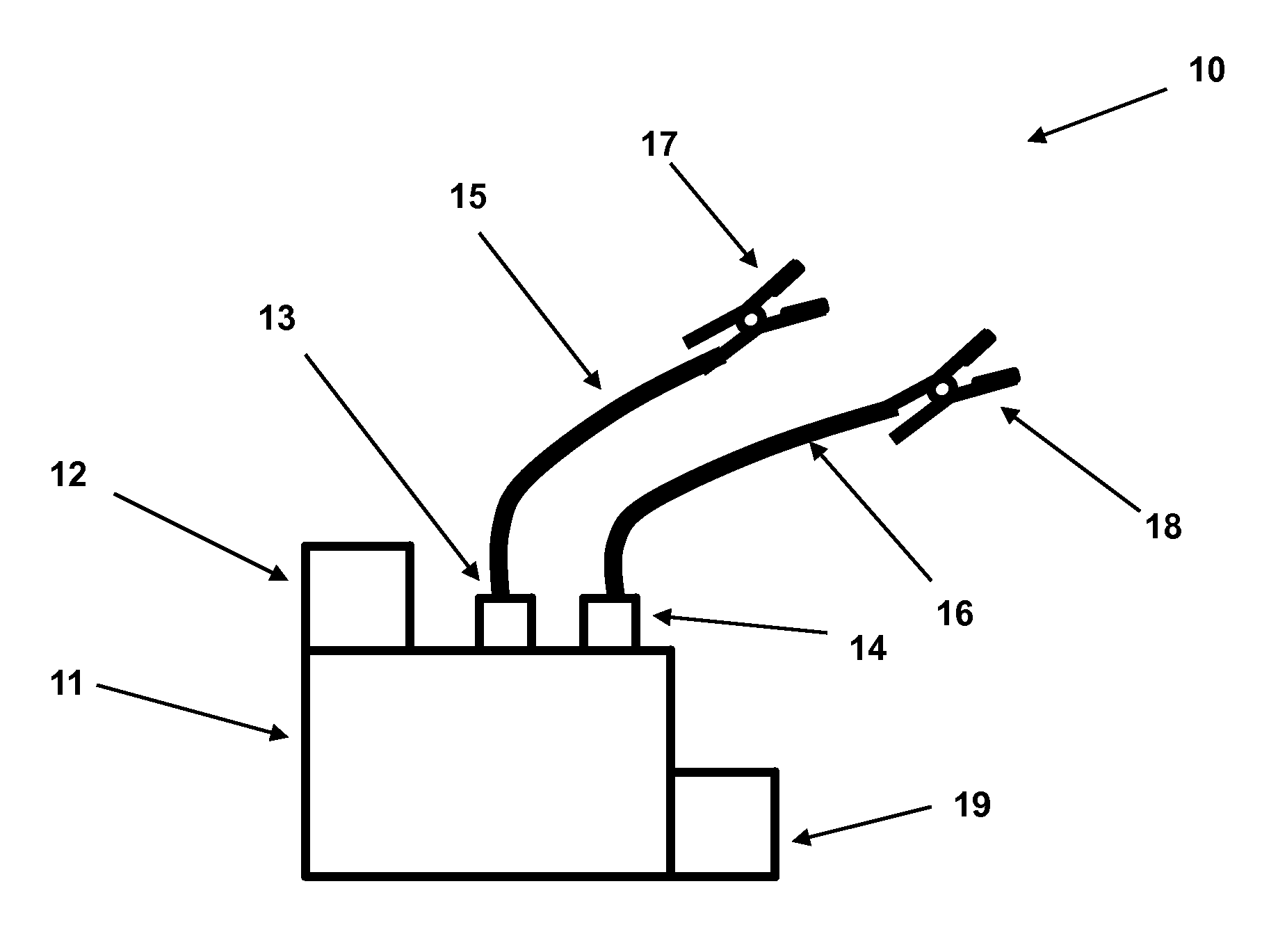
A reserve power source for charging a device, such as a depleted power source or a vehicle. The reserve power source including: a reserve battery which requires activation to produce power, such as a thermal battery or a liquid reserve battery; an activator for activating the reserve power upon one of an electrical or mechanical activation; and a pair of terminals operatively connected to the reserve battery for outputting the produced power. The reserve power source can also include a cable connected to each of the pair of terminals for connecting outputting the produced power to the depleted power source and / or conditioning circuitry for conditioning the produced power prior to output at the terminals. The reserve battery can also include a stop for preventing the activator from activating the reserve power source, where the stop is selectively removable when activation is desired.

Description

BACKGROUND OF THE INVENTION[0001]1. Field of the Invention[0002]The present invention relates to devices for starting engines in cars and other vehicles, emergency generators and the like, with self-contained very long lasting reserve power sources and their means of activation and electrical storage and regulation.[0003]2. Prior Art[0004]A motor vehicle storage battery frequently falls into a state of discharge such that it cannot deliver sufficient current to the starter motor. This is often due to lights or other accessories being accidently left on. Also, defective vehicle charging systems or the age of the battery can result in the same problem. To start the engine of a vehicle, generator or the like whose storage battery has been partially or completely discharged requires either by-passing the electrical starting system entirely or supplying the electrical starting system with an additional source of external electrical power.[0005]The former technique is generally accomplish...

Claims


Application Information

Patent Timeline
IPC IPC(8): H02J7/34H01M6/32H01M6/30
CPCF02N11/0866H01M6/30H01M2220/20H01M6/36H01M6/32
Inventor RASTEGAR, JAHANGIR S.
Owner OMNITEK PARTNERS LLC
Features
  • Generate Ideas
  • Intellectual Property
  • Life Sciences
  • Materials
  • Tech Scout
  • Unparalleled Data Quality
  • Higher Quality Content
  • 60% Fewer Hallucinations
Learn More