
Fluid stream imaging apparatus

a fluid stream and imaging apparatus technology, applied in the field of flow cytometry, can solve the problems of inability to achieve the precision required to achieve extremely accurate sorting decisions, time-consuming manual protocols, droplets downstream of nozzles, etc., and achieve accurate break off points and drop delays.

Active Publication Date: 2012-08-09
CYTONOMEST
View PDF5 Cites 55 Cited by
  • Summary
  • Abstract
  • Description
  • Claims
  • Application Information

AI Technical Summary

Benefits of technology

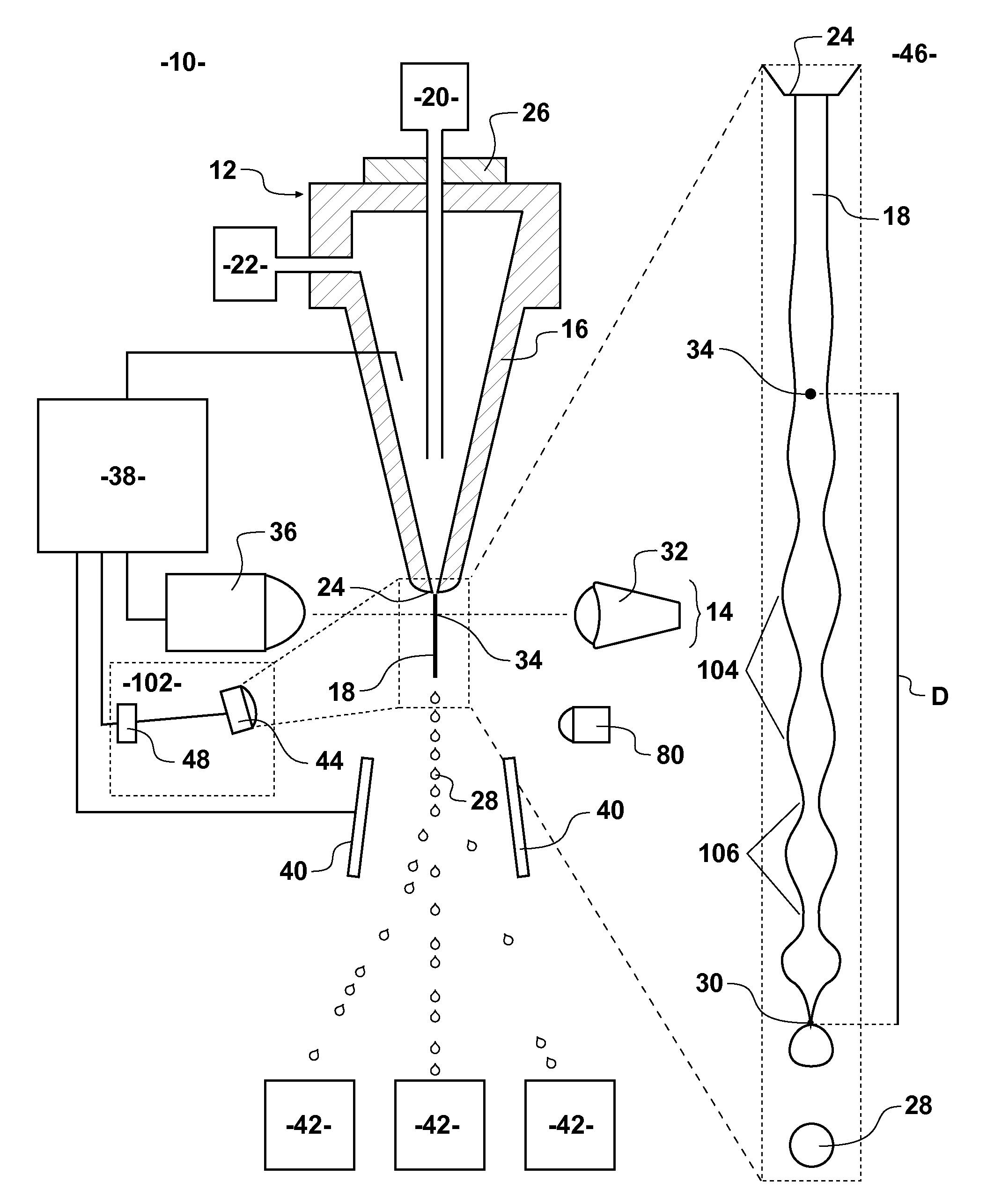
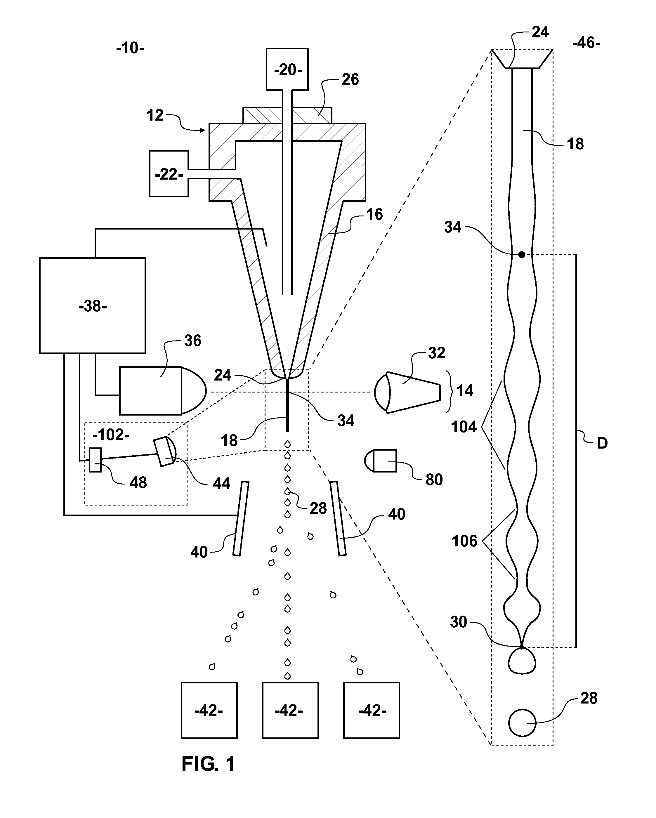
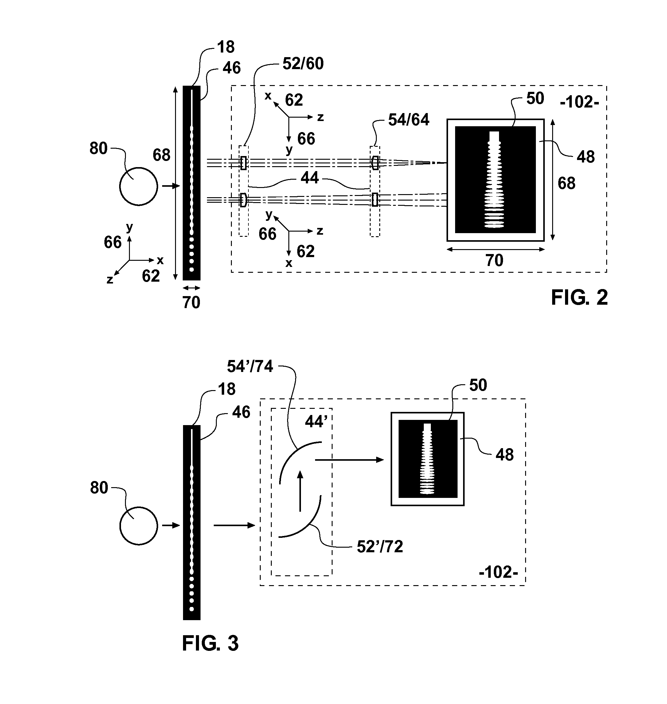
[0008]Certain aspects of this disclosure relate to an improved system for imaging a fluid stream, such as in a flow cytometer for analyzing and / or sorting particles. The provisions of such a system, in one embodiment include: a fluid delivery system having a nozzle for producing a fluid stream, the fluid delivery system having an oscillator for perturbing the fluid stream into droplets at a break off point downstream of the nozzle; an excitation energy source for interrogating the fluid stream at an inspection zone; an optical system for manipulating the aspect ratio of an image of the fluid stream; and a sensing element for sensing the manipulated image of the fluid stream. Such a system may be capable of producing an image of a fluid stream with sufficient detail along the flow axis of the stream and across the flow axis of the stream for deriving an accurate break off point and an accurate drop delay.
[0011]One broad object provided in this disclosure can be a camera to produce a single image of a fluid stream, where that image includes both an interrogation point, or inspection zone, and the break off point, and where the necks of forming droplets are captured with sufficient resolution across the flow axis (stream width) for precisely determining or updating a drop delay. From this image changes in the distance from the inspection zone to the break off point may provide more accurate drop delay information than previous systems.
[0012]An object of this disclosure can be to provide an apparatus and method for performing more accurate sort actions by precisely monitoring the fluid stream. Specifically, one broad object of the apparatus provided herein is to provide the capability for manipulating an image of the entire fluid stream into a format allowing important features throughout the entire fluid stream to be monitored in real time.

Problems solved by technology

The coaxial fluid stream may be perturbed with an oscillator, such as a piezoelectric crystal, resulting in the formation of droplets downstream of a nozzle.
Such manual protocols are time intensive and may be lacking in the precision required to achieve extremely accurate sort decisions and are incapable of real time verifications or adjustments.
However, the formation of droplets may not be so easily predictable and because only a portion of the stream is monitored, upstream changes may not be detected reliably.
This configuration provides for means of producing a composite image of the entire fluid stream, but is lacking the ability to monitor the fluid stream in real time because the camera must traverse the fluid stream at a rate thousands of times slower than the fluid stream itself.
Further, a stitched together image may not accurately reflect the stream at any particular time and is time consuming to produce.
Positional changes in the excitation source or the droplet break off point during operation, upon start up, or during other changes cannot quickly be realized by the described system because a series of images must first be captured and then stitched together.

Method used


Image

  • Fluid stream imaging apparatus
  • Fluid stream imaging apparatus
  • Fluid stream imaging apparatus

Examples


Embodiment Construction

[0023]The embodiments described herein relate to the analysis and sorting of particles, such as by flow cytometry. A number of inventive concepts provided below may be combined or applied to sorting systems other than flow cytometers.

[0024]Now referring primarily to FIG. 1, an example of a flow cytometer 10 is illustrated as a jet-in-air flow cytometer. The flow cytometer 10 may include a fluid delivery system 12, such as a nozzle 16 having a nozzle orifice 24 for delivering a fluid stream 18 to a detection system 14. The fluid stream 18 may be perturbed into droplets 28 by an oscillator 26. The droplets 28 may pass through an electromagnetic field produced by deflection plates 40. A charge applied to each droplet 28 will define a path into one of one or more collection containers 42.

[0025]The fluid stream 18 may comprise a coaxial fluid steam having an inner core stream of sample 20 and an outer stream of sheath fluid 22. The fluid stream 18 may exit the nozzle orifice 24 with incr...


PUM


Abstract

A fluid stream imaging apparatus having either optics for manipulating the aspect ratio or sensing elements configured for manipulating the aspect ratio of an image of the fluid stream. This application may also relate to a system for acquiring images of a portion of a fluid stream at high speeds for image processing to measure and predict droplet delays for individual forming particles.

Description

[0001]This application claims the benefit of U.S. Provisional Patent Application 61 / 439,757, filed on Feb. 4, 2011, the entire contents of which are incorporated herein by reference.FIELD[0002]The present disclosure generally relates to the field of flow cytometry, and more particularly a fluid stream imaging apparatus.BACKGROUND[0003]Various flow cytometers and microfluidic systems exist for the purpose of analyzing and sorting particles. Each of these instruments has various shortcomings relating to their ability to maintain accurate sort actions. Jet-in-air flow cytometers are commonly used for the purpose of sorting particles based on detected characteristics. The operation of a jet-in-air flow cytometer may involve producing a coaxial fluid stream in a nozzle. The coaxial fluid stream has a core stream of sample, which includes the particles or interest, and an outer stream of sheath fluid. The sheath fluid provides a means for positioning particles and preventing clogging in t...

Claims


Application Information

Patent Timeline
IPC IPC(8): G01N21/59
CPCG01N15/1404G01N15/1434G01N15/14G01N2015/149G01N2015/1406G01N2015/144G01N1/08G01N15/149
Inventor SHARPE, JOHNATHAN CHARLESPERRAULT, JR., DONALD FRANCISSEDOGLAVICH, NEMANYA
Owner CYTONOMEST
Learn More