Magnetic integration double-ended converter

a converter and double-ended technology, applied in the direction of electric variable regulation, process and machine control, instruments, etc., can solve the problems of large leakage inductance and significant loss of windings in the prior art, and achieve high-efficiency energy conversion and reduce the loss of windings and leakage inductan

Active Publication Date: 2012-08-09
HUAWEI TECH CO LTD
View PDF5 Cites 14 Cited by
  • Summary
  • Abstract
  • Description
  • Claims
  • Application Information

AI Technical Summary

Benefits of technology

[0006]Embodiments of the present application provide a magnetic integration double-ended converter, capable of reducing a loss ...

Problems solved by technology

During implementation application, the above prior art at least has the ...

Method used


Image

  • Magnetic integration double-ended converter
  • Magnetic integration double-ended converter
  • Magnetic integration double-ended converter

Examples


embodiment 1

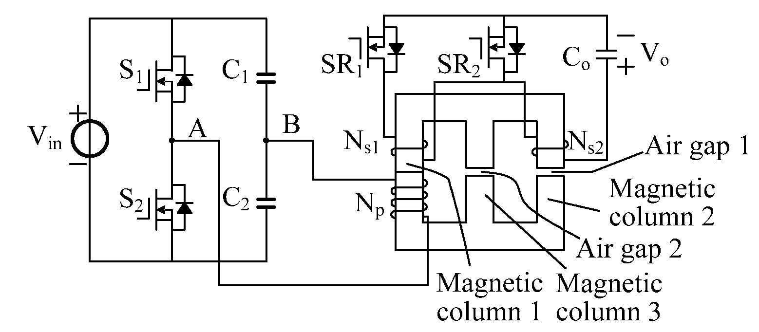
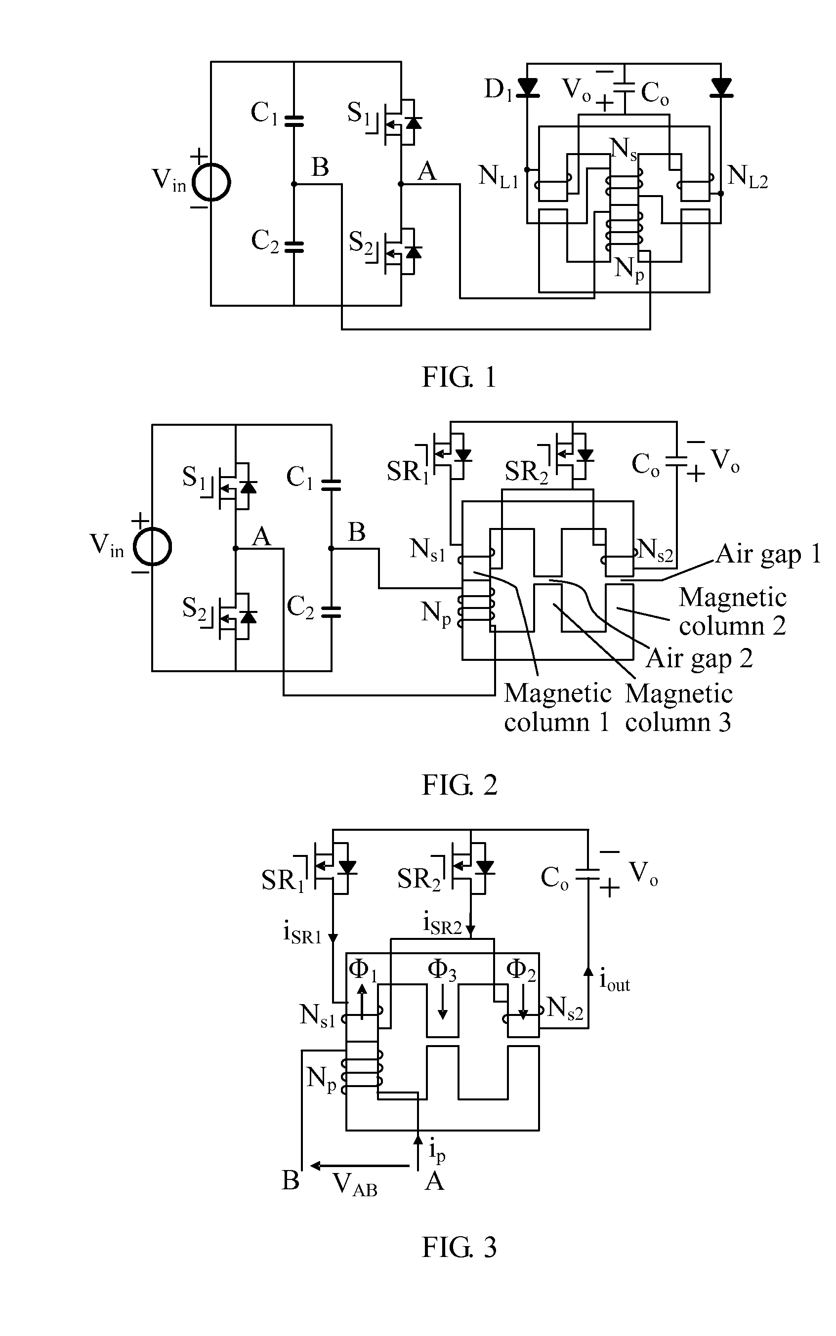
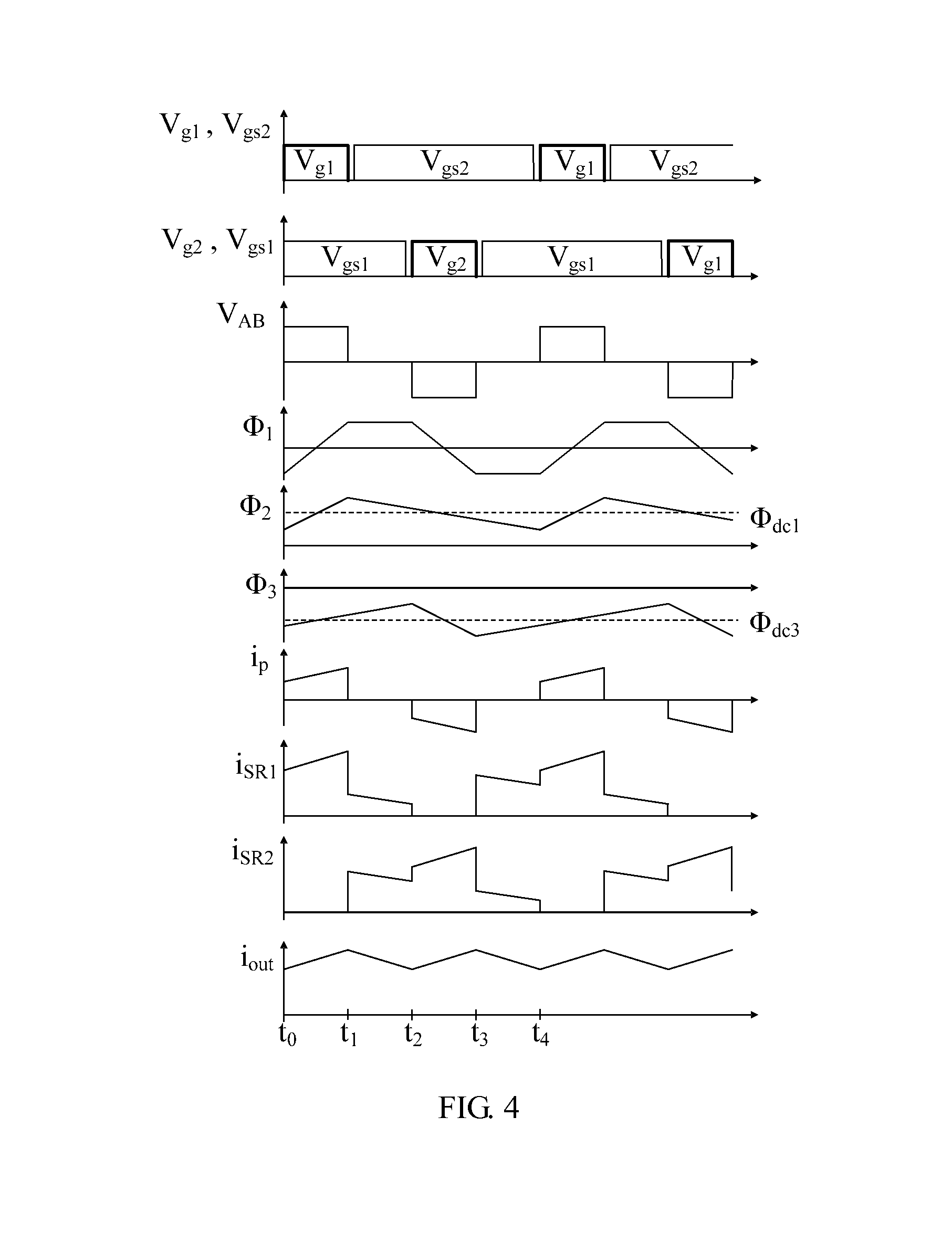
[0036]FIG. 2 shows a magnetic integration half-bridge converter in Embodiment 1, where a half-bridge inverter circuit on a primary side includes voltage dividing capacitors C1 and C2 and power switch diodes S1 and S2. An integrated magnetic member of the magnetic integration half-bridge converter includes an EE-type magnetic core. The EE-type magnetic core includes three windings and two energy storage air gaps. A primary winding Np and a first secondary winding Ns1 are wound around a first magnetic column 1, a second secondary winding Ns2 is wound around a second magnetic column 2, an energy storage air gap 1 is disposed on the second magnetic column 2, and an energy storage air gap 2 is disposed on a third magnetic column 3. Two ends of the primary winding Np are respectively connected to a connection point A of bridge arms of the power switch diodes S1 and S2 of the half-bridge inverter circuit and a connection point B of the voltage dividing capacitors C1 and C2 of the half-brid...

embodiment 2

[0044]FIG. 5 shows a magnetic integration half-bridge converter of Embodiment 2. The difference between the magnetic integration half-bridge converter of Embodiment 2 and the magnetic integration half-bridge converter of Embodiment 1 is that, an EE-type magnetic core of Embodiment 2 includes three windings and one energy storage air gap. A primary winding Np and a first secondary winding Ns1 are wound around a first magnetic column 1, a second secondary winding Ns2 is wound around a second magnetic column 2, an energy storage air gap 1 is disposed on a third magnetic column 3, and the number of turns of the first secondary winding Ns1 is twice the number of turns of the second secondary winding Ns2.

[0045]Referring to FIG. 5, a working process of the circuit of Embodiment 2 may also be divided into four stages:

[0046]Stage 1 [t0-t1]: The power switch diode S1 on the primary side is turned on and S2 is turned off, and the synchronous rectifier SR1 on the secondary side is turned on and...

embodiment 3

[0052]FIG. 7 shows a magnetic integration half-bridge converter of Embodiment 3. On the basis of Embodiment 2, a third secondary winding Ns3 is added on a third magnetic column 3. Specifically, an EE-type magnetic core of Embodiment 3 includes four windings and one energy storage air gap. A primary winding Np and a first secondary winding Ns1 are wound around a first magnetic column 1, a second secondary winding Ns2 is wound around a second magnetic column 2, the third winding Ns3 is wound around the third magnetic column 3, an energy storage air gap 1 is defined in the third magnetic column 3, and the number of turns of the first secondary winding Ns1 is twice the number of turns of the second secondary winding Ns2.

[0053]In this case, the first secondary winding Ns1, the second secondary winding Ns2, the third secondary winding Ns3, an output filtering capacitor Co, and a first synchronous rectifier SR1 form a power circuit on the secondary side; the second secondary winding Ns2, t...


PUM


Abstract

A magnetic integration double-ended converter with an integrated function of a transformer and an inductor includes an integrated magnetic member having a magnetic core with three magnetic columns having at least three windings (NP, NS1, NS2) and at least one energy storage air gap, where a primary winding (NP) and a first secondary winding (NS1) are both wound around a first magnetic column or are both wound around a second magnetic column and a third magnetic column, and a second secondary winding (NS2) is wound around the second magnetic column; an inverter circuit with double ends symmetrically working, acting on the primary winding (NP); and a group of synchronous rectifiers (SR1, SR2), gate electrode driving signals of which and gate electrode driving signals of a group of power switch diodes (S1, S2) of the inverter circuit with the double ends symmetrically working complement each other.

Description

CROSS-REFERENCE TO RELATED APPLICATIONS[0001]This application is a continuation of International Application No. PCT / CN2011 / 070353, filed on Jan. 18, 2011, which claims priority to Chinese Patent Application No. 201010004094.1, filed on Jan. 19, 2010 and Chinese Patent Application No. 201010266511.X, filed on Aug. 30, 2010, all of which are hereby incorporated by reference in their entireties.FIELD OF THE APPLICATION[0002]The present application relates to a magnetic integration double-ended converter with an integrated function of a transformer and an inductor.BACKGROUND OF THE APPLICATION[0003]In an application scenario of direct-current converter with a wide-range input voltage, according to requirements of a power level, a single-ended converter (such as a flyback converter or a forward converter) or a double-ended converter (such as a half-bridge converter, a full-bridge converter, or a push-pull converter) may be used as a main power topology.[0004]FIG. 1 shows an existing mag...

Claims


Application Information

Patent Timeline
IPC IPC(8): H02M3/335
CPCH01F3/14H01F27/38H02M3/28H02M3/3376H02M2001/0064Y02B70/1475H02M3/33592H02M1/0064Y02B70/10
Inventor LU, ZENGYIZHU, YONGFABAI, YADONGCHEN, WEIJIN, ZHAOGUO
Owner HUAWEI TECH CO LTD
Why Eureka
Try Eureka