Access control system, access control method, relay station apparatus, terminal station apparatus, transmitting side processing method, receiving side processing system, and receiving side processing method

a technology of access control and relay station, applied in the field of access control system, can solve problems such as the employment of network encoding technology, and achieve the effect of reducing the probability of packet collision and improving system throughpu

Active Publication Date: 2012-08-09
NIPPON TELEGRAPH & TELEPHONE CORP
View PDF9 Cites 25 Cited by
  • Summary
  • Abstract
  • Description
  • Claims
  • Application Information

AI Technical Summary

Benefits of technology

[0030]In a wireless relay system according to the present invention, a plurality of relay stations relay communication between two terminal stations that perform random access. The terminal stations and the relay stations include a slot synchronization unit, a time synchronization unit, and a transmission unit. The slot synchronization unit synchronizes slot timing of a time slot indicating a unit time. The time synchronization unit performs time synchronization to synchronize the slot timing. The transmission unit transmits a transmission packet to a wireless line in synchronization with the slot timing. A transmission right is allocated for at least one time slot to each of a pl

Problems solved by technology

It is to be noted that this conventional scheme does not emplo

Method used


Image

  • Access control system, access control method, relay station apparatus, terminal station apparatus, transmitting side processing method, receiving side processing system, and receiving side processing method
  • Access control system, access control method, relay station apparatus, terminal station apparatus, transmitting side processing method, receiving side processing system, and receiving side processing method
  • Access control system, access control method, relay station apparatus, terminal station apparatus, transmitting side processing method, receiving side processing system, and receiving side processing method

Examples


first embodiment

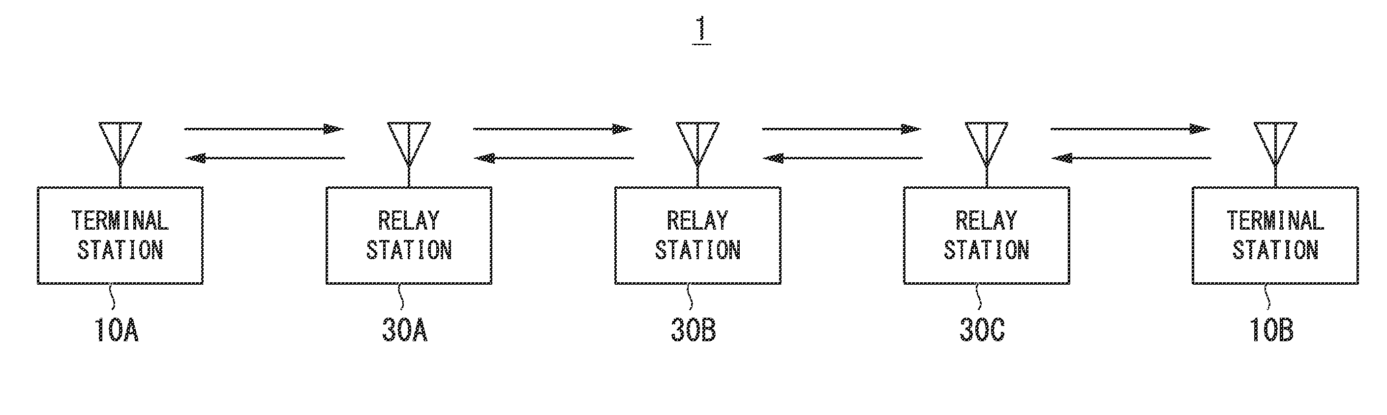
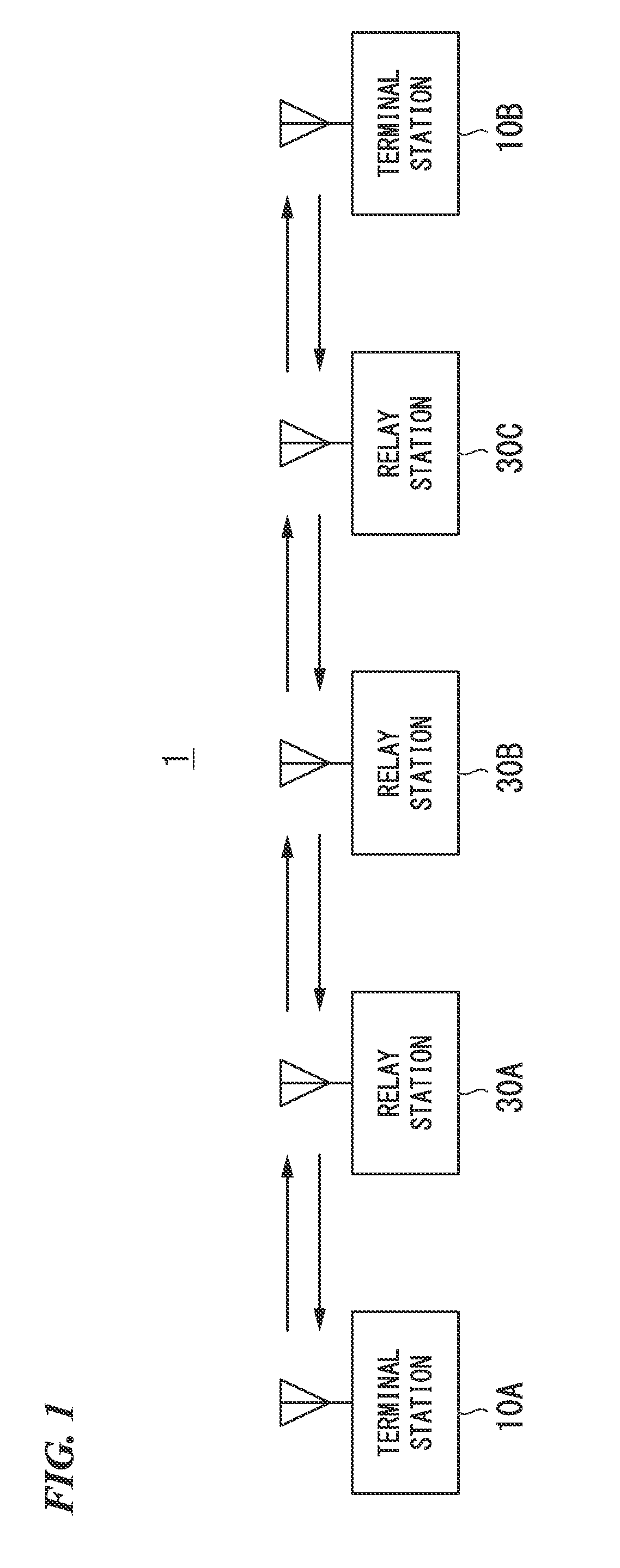
[0052]FIG. 1 is a configuration diagram illustrating a configuration of a wireless relay system in accordance with the present embodiment.

[0053]A wireless relay system 1 illustrated in this drawing includes terminal stations 10A and 10B (also collectively referred to as terminal stations 10) and relay stations 30A, 30B, and 30C (also collectively referred to as relay stations 30).

[0054]The terminal stations 10A and 10B are wireless terminals of which communication is relayed instead of performing direct communication, and which communicate with each other. The terminal stations 10A and 10B perform a communication process, for example, when they are located in positions between which radio waves do not reach or when they are placed in a situation in which it is difficult to perform direct communication.

[0055]The relay stations 30 are arranged between the terminal stations 10A and 10B, and the relay stations 30 relay communication between the terminal stations 10A and 10B. In the wire...

second embodiment

[0097]The assignment of transmission rights in a wireless relay system in accordance with the present embodiment will be shown.

[0098]FIG. 7 is a timing chart illustrating the use of time slots of the wireless relay system in accordance with the present embodiment.

[0099]Relay stations 30 illustrated in this drawing are controlled by a wireless relay scheme in which an odd-numbered relay station 30 can only perform transmission at a time of an odd-numbered time slot, and an even-numbered relay station 30 can only perform transmission at a time of an even-numbered time slot. This scheme is applied to a model in which radio waves transmitted by a station itself interferes with those of an adjacent station, but the radio waves of the station itself do not interfere with those of a next adjacent station, thereby making it possible to avoid packet collisions between the relay stations 30 even when each relay station 30 transmits a packet in accordance with the random access scheme.

[0100]Th...

third embodiment

[0104]The assignment of transmission rights in a wireless relay system in accordance with the present embodiment will be shown.

[0105]FIG. 8 is a timing chart illustrating the use of time slots of the wireless relay system in accordance with the present embodiment.

[0106]Relay stations 30 illustrated in this drawing are controlled by a wireless relay scheme in which an even-numbered relay station 30 can only perform transmission at a time of an odd-numbered time slot, and an odd-numbered relay station 30 can only perform transmission at a time of an even-numbered time slot. This scheme is applied to a model in which radio waves transmitted by a station itself interfere with those of an adjacent station, but the radio waves of the station itself do not interference with those of a next adjacent station, thereby making it possible to avoid packet collisions between the relay stations 30 even when each relay station 30 transmits a packet in accordance with the random access scheme.

[0107]...


PUM


Abstract

Provided is a wireless relay system that improves system throughput between terminal stations and flexibly makes system throughput variable with respect to short-term traffic fluctuations. In the wireless relay system, a plurality of relay stations relay communication between two terminal stations that perform random access. The terminal stations and the relay stations include a slot synchronization unit, a time synchronization unit, and a transmission unit. The slot synchronization unit synchronizes slot timing of a time slot indicating a unit time. The time synchronization unit performs time synchronization for synchronization of the slot timing. The transmission unit transmits a transmission packet to a wireless line in synchronization with the slot timing. A transmission right is allocated for at least one time slot to each of a plurality of groups which are configured so that a group of a terminal station or a relay station and a group of an adjacent terminal station or an adjacent relay station are different from each other. The transmission unit transmits the transmission packet to the wireless line only in a time slot in which the transmission right is allocated to the group to which the terminal station or the relay station belongs.

Description

TECHNICAL FIELD[0001]The present invention relates to a wireless relay scheme of decreasing the collision probability of packet signals due to media access control between relay stations and of improving system throughput when communication is performed between terminal stations via multistage relay stations in a digital wireless-relay communication system using random access as a basic media access control scheme.[0002]Priority is claimed on Japanese Patent Application No. 2009-244526 filed Oct. 23, 2009, and the content of which is incorporated herein by reference.BACKGROUND ART[0003]There is a communication protocol of a wireless relay scheme that is applied to a digital wireless-relay communication system using random access as a basic media access control scheme.[0004]For example, a communication protocol of a wireless relay scheme reported in Non-patent Document 1 is based on Association of Radio Industries and Businesses (ARIB) standard STD-T67, which is a standard protocol f...

Claims


Application Information

Patent Timeline
IPC IPC(8): H04B7/14H04W72/04H04W56/00
CPCH04B7/155H04B7/15521H04B7/2606H04W72/082H04W56/00H04W72/04H04W84/047H04B7/2656H04W88/04H04W72/541H04W16/26H04W74/00
Inventor SUGIYAMA, TAKATOSHIUMEHARA, DAISUKETANAKA, MASAAKI
Owner NIPPON TELEGRAPH & TELEPHONE CORP
Why Eureka
Try Eureka