Decision feedback equalizer and transceiver

a feedback equalizer and transceiver technology, applied in the field of equalizers, transmitters and receivers, can solve the problem of limiting the bandwidth of existing backplanes, and achieve the effect of reducing the cost of operation and maintenan

Active Publication Date: 2012-08-09
RAMBUS INC
View PDF5 Cites 106 Cited by
  • Summary
  • Abstract
  • Description
  • Claims
  • Application Information

AI Technical Summary

Benefits of technology

[0028]In another aspect, the disclosure describes a decision feedback equalizer having at least one comparator, the at least one comparator comprising a first stage, comprising a main branch having two track switches with a resistive load, an offset cancellation branch, a plurality of tap branches with transistor sizes smaller than the main bran...

Problems solved by technology

Bandwidth limitation of existing backplanes has become an obstacle...

Method used


Image

  • Decision feedback equalizer and transceiver
  • Decision feedback equalizer and transceiver
  • Decision feedback equalizer and transceiver

Examples


Embodiment Construction

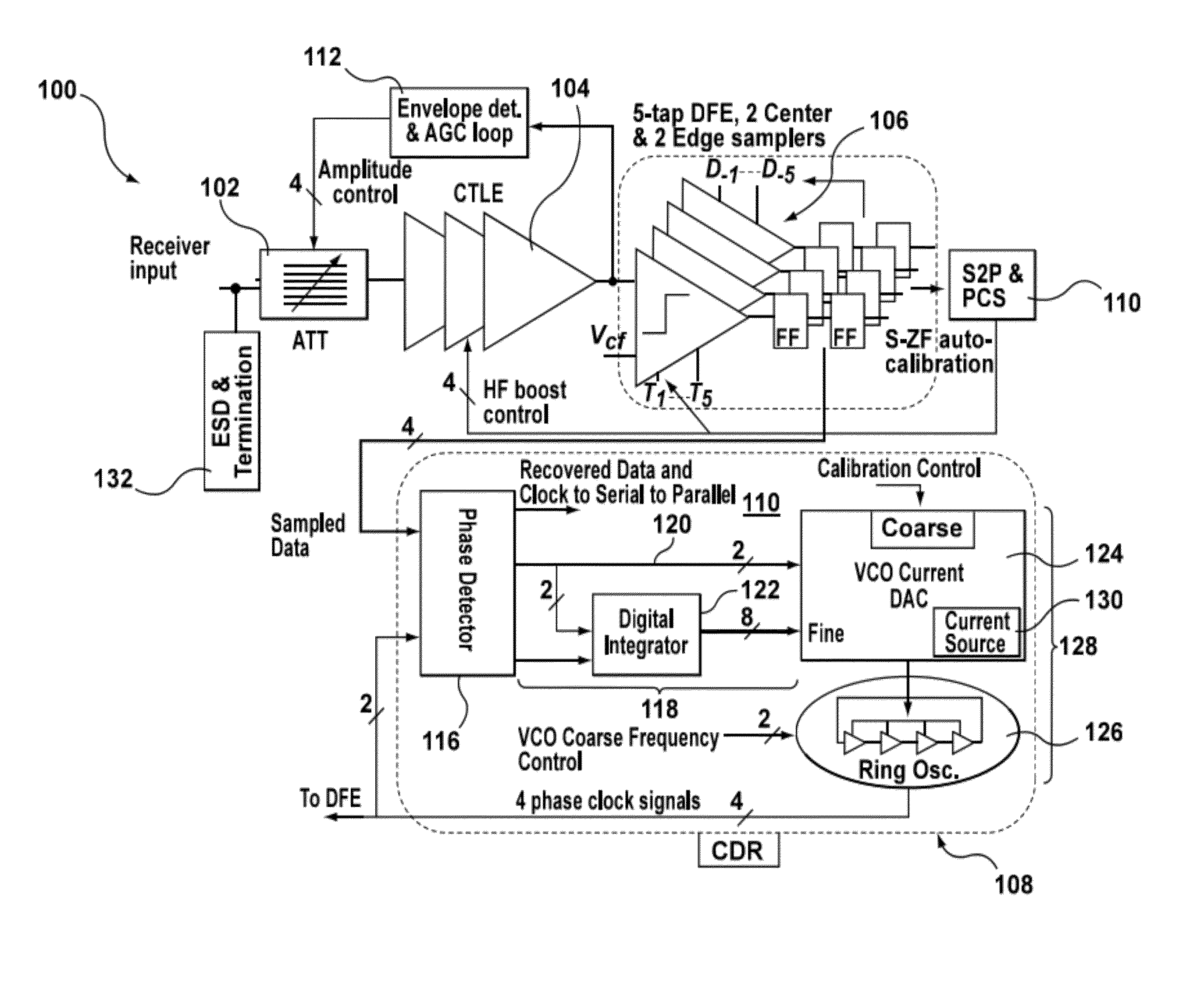
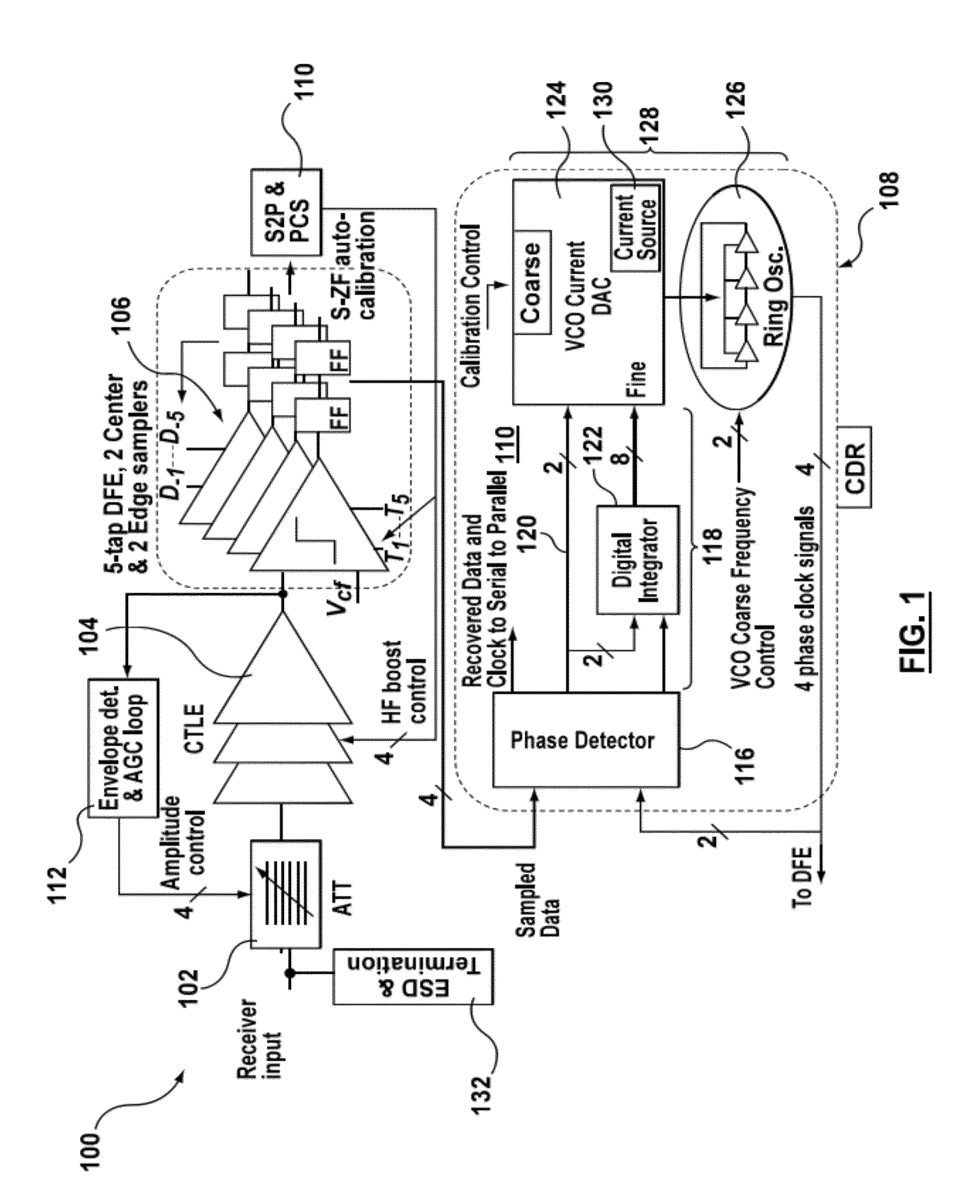
[0038]According to example embodiments, in order to compensate for bandwidth limitation of backplanes, a transceiver that employs a combination of Tx pre-emphasis, an advanced Rx continuous time linear equalizer (CTLE) and a decision feedback equalizer (DFE) can be used. In one example embodiment, this description presents a 4-lane transceiver implemented in 40 nm CMOS (Complementary metal-oxide-semiconductor) technology that operates over a wide range of data rates from 1 to 12 Gbps (48 Gbps aggregated) using NRZ (non-return to zero) coding. The supply voltages are 0.9V and 1.8V. In an example embodiment, an innovative algorithm, as described in greater detail below, is used to adapt the CTLE and DFE to cancel the channel ISI (inter-symbol interference). In at least some examples, no inductors are used in the transceiver and ring oscillators are used for both the Tx and Rx clock generation. In some applications, this may provide a wide frequency tuning range, small layout area, and...


PUM


Abstract

A decision feedback equalizer, transceiver, and method are provided, the equalizer having at least one comparator, the at least one comparator comprising a first stage, comprising a main branch having two track switches with a resistive load, an offset cancellation branch, a plurality of tap branches with transistor sizes smaller than the main branch, in which previous decisions of the equalizer are mixed with the tap weights using current-mode switching, and a cross coupled latch branch; and a second stage, comprising a comparator module for making decisions based on the outputs of the first stage and a clock input, and a plurality of flip-flops for storing the output of the comparator module.

Description

[0001]This application claims the benefit of and priority to U.S. Patent Application Ser. No. 61 / 382,476, filed Sep. 13, 2010, the contents of which are incorporated herein by reference.BACKGROUND[0002]This disclosure relates to equalizers, transmitters and receivers.[0003]Bandwidth limitation of existing backplanes has become an obstacle to meet the increasing demand for high data rate wireline transmission.BRIEF DESCRIPTION OF THE DRAWINGS[0004]Example embodiments will be described with reference to the following Figures:[0005]FIG. 1 is block diagram of a receiver according to an example embodiment;[0006]FIG. 2 is an abbreviated front-end schematic of a receiver attenuator according to an example embodiment, omitting stages 2 through 15;[0007]FIG. 3 is a schematic of a continuous time linear equalizer according to an example embodiment;[0008]FIG. 4 is an abbreviated schematic of a DFE comparator according to an example embodiment, showing a first tap branch but omitting tap branch...

Claims


Application Information

Patent Timeline
IPC IPC(8): H03H7/40H03H7/30
CPCH04L25/0272H04L2025/03624H04L25/03057H04L25/0276
Inventor ABDALLA, MOHAMEDREZAYEE, AFSHINCASSAN, DAVIDVAN IERSSEL, MARCUSHOLDENRIED, CHRISSADR, SAMAN
Owner RAMBUS INC
Why Eureka
Try Eureka