Ex-core nuclear instrumentation system

a nuclear instrumentation system and core technology, applied in nuclear elements, climate sustainability, greenhouse gas reduction, etc., can solve the problems of inability to obtain output voltage level (3.3 v being amplified) and achieve high-quality measurement value

Active Publication Date: 2012-08-09
MITSUBISHI ELECTRIC CORP
View PDF7 Cites 26 Cited by
  • Summary
  • Abstract
  • Description
  • Claims
  • Application Information

AI Technical Summary

Benefits of technology

[0015]According to an ex-core nuclear instrumentation system of the present invention, even when a neutron detector current is minute, a voltage level capable of

Problems solved by technology

For this reason, a problem exists in that, even when a neutron detector current is amplified by the detector signal processing circuit 8 correspon

Method used


Image

  • Ex-core nuclear instrumentation system
  • Ex-core nuclear instrumentation system
  • Ex-core nuclear instrumentation system

Examples


embodiment 1

Preferred Embodiment 1

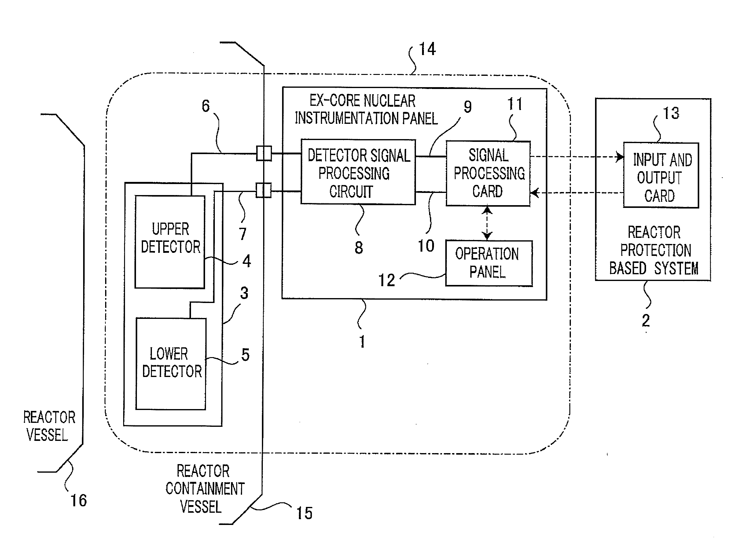
[0022]FIG. 5 is a configuration diagram showing a general configuration of an ex-core nuclear instrumentation system in an output range. In FIG. 5, a neutron detector 3 of an ex-core nuclear instrumentation system 14 is provided around outside a reactor vessel 16 which is to be located in a reactor containment vessel 15. The neutron detector 3 is one in which an upper detector 4 and a lower detector 5 are integrated. The upper detector 4 detects a neutron leaked from an upper part of the reactor vessel 16 and converts the same into a current value; and the lower detector 5 detects a neutron leaked from a lower part of the reactor vessel 16 and converts the same into a current value. The current value converted by the upper detector 4 is inputted to a detector signal processing circuit 8 located in an ex-core nuclear instrumentation panel 1 of the ex-core nuclear instrumentation system 14 via an upper detector cable 6, the ex-core nuclear instrumentation panel 1...

embodiment 2

Preferred Embodiment 2

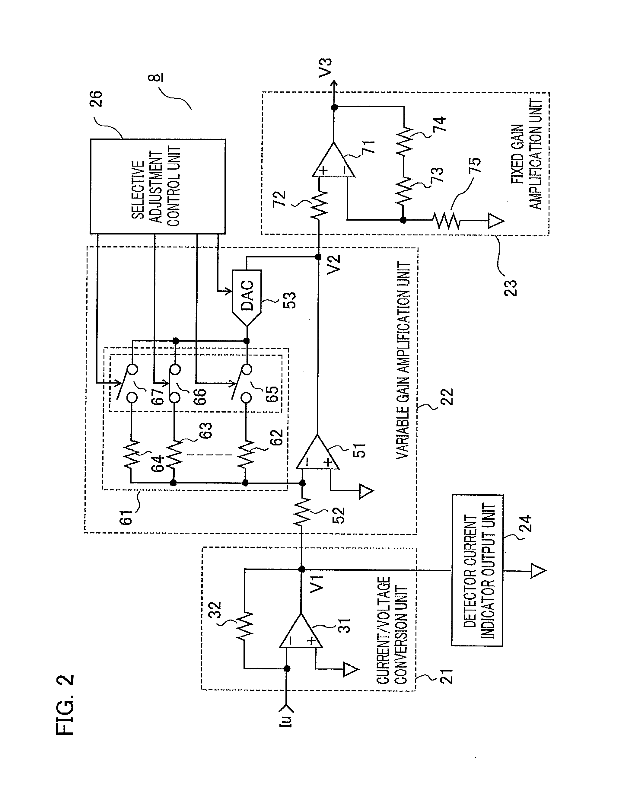
[0034]FIG. 3 is a circuit configuration diagram showing a detector signal processing circuit (I / E amplifier) 8 in a preferred embodiment 2. In the preferred embodiment 1, the description has been made on the case where switching control is performed by adding the resistance circuit for corresponding to current levels 61 composed of the resistors and the analog switches to the variable gain amplification unit 22; however, in the preferred embodiment 2, as shown in FIG. 3, a resistance circuit for corresponding to current levels 41 composed of resistors and analog switches is added to a current / voltage conversion unit 21 with respect to the basic circuit configuration diagram of FIG. 1. Incidentally, reference numerals 42 to 44 denote resistors and 45 to 47 denote analog switches. A resistance value in the resistance circuit for corresponding to current levels 41 is selectively switched by a selective adjustment control unit 27 by indication of a detector current...

embodiment 3

Preferred Embodiment 3

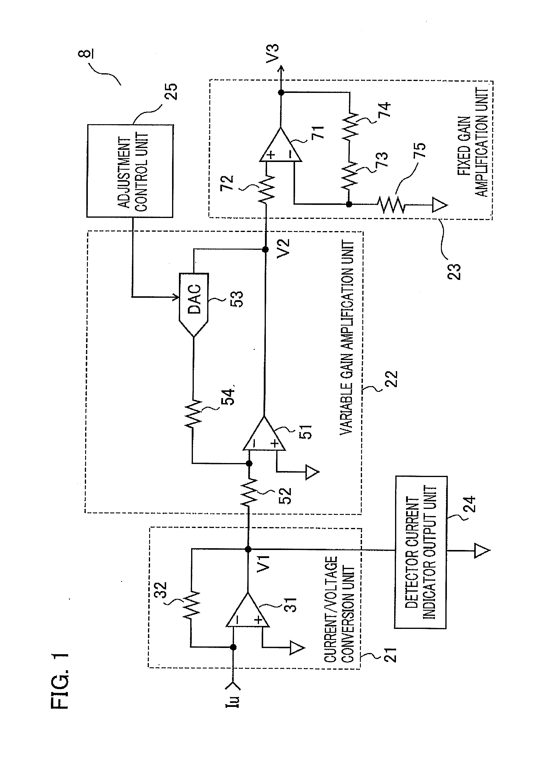
[0036]FIG. 4 is a circuit configuration diagram showing a detector signal processing circuit (I / E amplifier) 8 in a preferred embodiment 3. As shown in FIG. 4, D / A converters 55 (DAC1) and 56 (DAC2) are connected in series so that the D / A converters of a variable gain amplification unit 22 are configured in two steps with respect to FIG. 1.

[0037]One D / A converter 55 corresponds to the resistance circuit for corresponding to current levels 61 of the preferred embodiment 1 and largely selects a resistance value by a selective adjustment control unit 28; and the other D / A converter 56 corresponds to the D / A converter 53 of the preferred embodiment 1 and finely adjusts the resistance value by the selective adjustment control unit 28. For this reason, a gain of the variable gain amplification unit, that is, the width of a gain of the detector signal processing circuit can be largely and accurately changed as compared before by selective adjustment control; and there...


PUM


Abstract

An ex-core nuclear instrumentation system in which the width of measurable neutron detector current can be accurately widened is obtained. In order to output the condition of neutron flux in operation by performing arithmetic processing of a current value measured by a neutron detector by using a detector signal processing circuit, the detector signal processing circuit includes a current/voltage conversion unit which converts the current value converted by the neutron detector into a voltage value corresponding to the current value; and a variable gain amplification unit which has an operational amplifier having a resistance circuit for corresponding to current levels, the resistance circuit being capable of selecting a gain, and a D/A converter that adjusts the gain, and amplifies the voltage value converted by the current/voltage conversion unit.

Description

BACKGROUND OF THE INVENTION[0001]1. Field of the Invention[0002]The present invention relates to an ex-core nuclear instrumentation system that monitors neutron flux outside a reactor vessel and, more particularly, relates to a detector signal processing circuit (I / E amplifier) to be located in an ex-core nuclear instrumentation panel that constitutes the ex-core nuclear instrumentation system.[0003]2. Description of the Related Art[0004]An ex-core nuclear instrumentation system continuously monitors neutron flux outside a reactor vessel of a pressurized water reactor (PWR) and accordingly the state of the reactor at start and in operation is monitored; and when an abnormality is detected in the condition of the neutron flux, the ex-core nuclear instrumentation system outputs an alarm signal and a signal for emergency shutdown of the reactor and accordingly the reactor is protected. The ex-core nuclear instrumentation system mainly includes a neutron detector that measures the neutr...

Claims


Application Information

Patent Timeline
IPC IPC(8): G21C17/108
CPCG21C17/108G01T1/17Y02E30/30
Inventor NAKAMURA, SHINGOKOBAYASHI, TATSURO
Owner MITSUBISHI ELECTRIC CORP
Why Eureka
Try Eureka