Estimating subject motion between image frames

a subject motion and image frame technology, applied in the field of digital imaging, can solve the problems of longer time base required to verify, and it is impossible to compute a motion value close to zero even where, so as to reduce the effects improve accuracy of motion estimates, and reduce the effect of image noise and motion variability

Inactive Publication Date: 2012-08-09
APPLE INC
View PDF5 Cites 36 Cited by
  • Summary
  • Abstract
  • Description
  • Claims
  • Application Information

AI Technical Summary

Benefits of technology

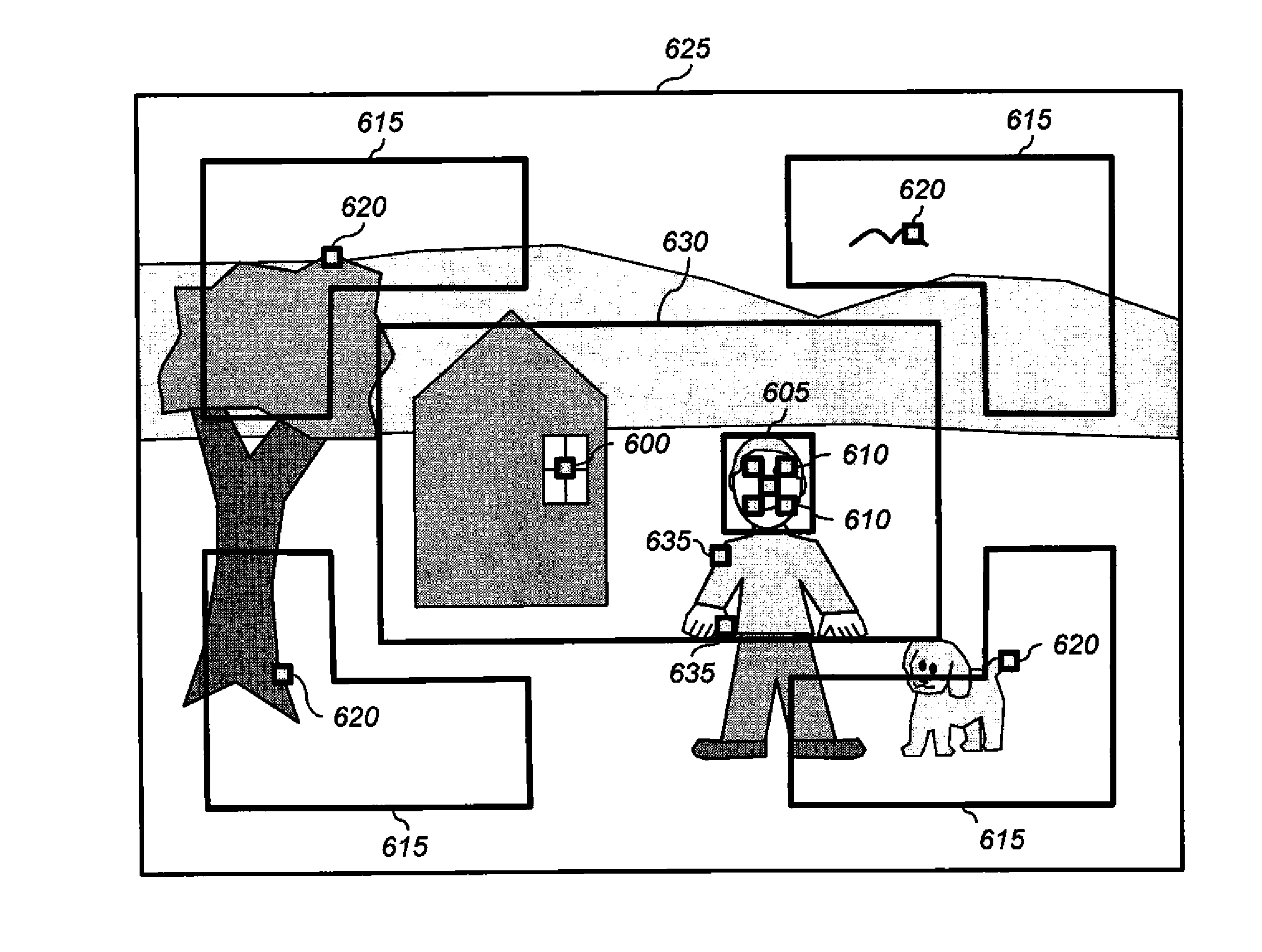
[0030]This invention has the advantage that it determines a spatial offset between two digital images with sub-pixel accuracy. The accuracy of the motion estimate is improved by combining motion estimates for a plurality of image regions, wherein higher weights are used for the motion estimates which are more likely to be accurate measures of the true motion.
[0031]It has the further advantage that the determined motion estimate can be used to determine image capture settings for capturing an archival digital image in a manner that accounts for the image motions that are most likely to affect perceived image quality.
[0032]It has the additional advantage that motion estimates can be determined for a plurality of image regions, and at a plurality of capture times in order to account for the local motion of objects within an image, and to reduce the effects of image noise and motion variability. Furthermore, the motion velocity can be adjusted to provide more accurate motion estimates in the presence of image noise.

Problems solved by technology

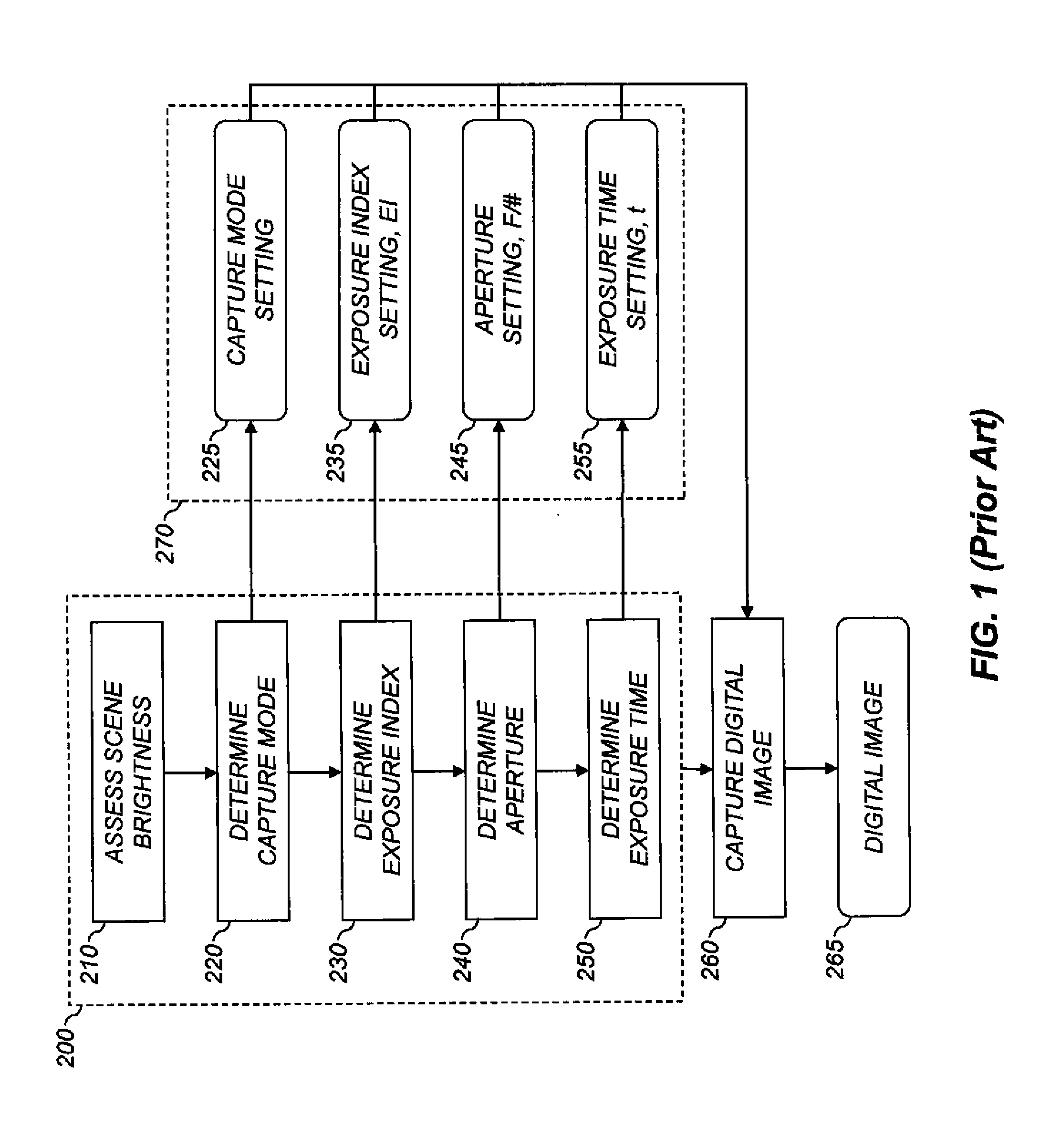
However, if the most recent motion velocity estimate indicates a low level of motion, a longer time base is required to verify that the scene is truly static.
Often for preview images with low signal-to-noise ratios, it is impossible to compute a motion value close to zero even where no motion exists.
This is a consequence of small random errors producing differences between the captured preview images.

Method used


Image

  • Estimating subject motion between image frames
  • Estimating subject motion between image frames
  • Estimating subject motion between image frames

Examples


Embodiment Construction

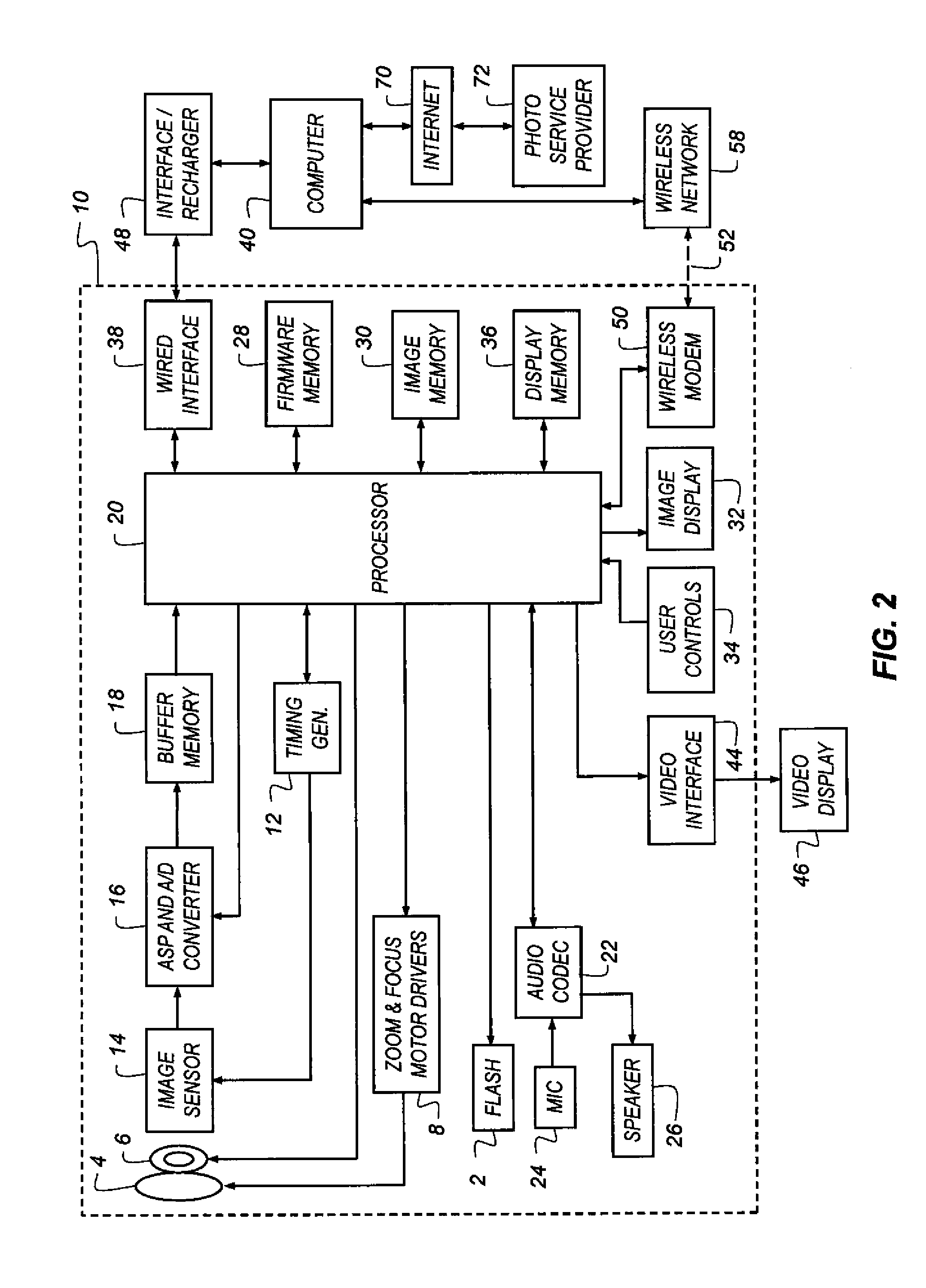
[0045]In the following description, a preferred embodiment of the present invention will be described in terms that would ordinarily be implemented as a software program. Those skilled in the art will readily recognize that the equivalent of such software can also be constructed in hardware. Because image manipulation algorithms and systems are well known, the present description will be directed in particular to algorithms and systems forming part of, or cooperating more directly with, the system and method in accordance with the present invention. Other aspects of such algorithms and systems, and hardware or software for producing and otherwise processing the image signals involved therewith, not specifically shown or described herein, can be selected from such systems, algorithms, components and elements known in the art. Given the system as described according to the invention in the following materials, software not specifically shown, suggested or described herein that is usef...


PUM


Abstract

A method for determining a motion estimate, comprising: capturing at least two digital images of a scene at different capture times; designating one of the digital images as a reference digital image; designating a plurality of image regions; determining motion estimates for each image region by shifting the image regions within the non-reference digital images according to each of a plurality of spatial offsets relative to the image region within the reference digital image, computing merit function values for each spatial offset providing an indication of a difference between the image region in the reference digital image and the shifted image regions, computing a fitting function that provides an estimated merit function value as a function of spatial offset; and determining the motion estimate responsive to the determined non-integer spatial offset. A combined motion estimate is determined using weighting coefficients determined responsive to the shapes of the fitting functions.

Description

CROSS-REFERENCE TO RELATED APPLICATIONS[0001]Reference is made to commonly assigned, co-pending U.S. patent application Ser. No. 12 / 701,659 (docket 95252), entitled: “Capture condition selection from brightness and motion”, by Pillman et al.; to commonly assigned, co-pending U.S. patent application Ser. No. 12 / 943,328 (Docket 96183), entitled “Automatic engagement of image stabilization,” by Stupak et al.; to commonly assigned, co-pending U.S. patent application Ser. No. 12 / 987,403 (docket 96451), entitled: “Combined ambient and flash exposure for improved image quality”, by Pillman et al.; and to commonly assigned, co-pending U.S. patent application Ser. No. ______ (docket 96768), entitled: “Estimating subject motion for exposure time determination”, by Jasinski et al., all of which are incorporated herein by reference.FIELD OF THE INVENTION[0002]This invention pertains to the field of digital imaging, and more particularly to a method for estimating subject motion between image fr...

Claims


Application Information

Patent Timeline
Patent Type & Authority Applications(United States)
IPC IPC(8): G06K9/00
CPCH04N5/235H04N5/2327H04N23/684H04N23/70
Inventor JASINSKI, DAVID WAYNEPILLMAN, BRUCE HAROLD
Owner APPLE INC
Why Eureka
Try Eureka