Rotor of a turbomachine compressor, with an optimised inner end wall

a turbomachine compressor and inner end wall technology, applied in the direction of liquid fuel engines, vessel construction, marine propulsion, etc., can solve the problems of supersonic shocks having an adverse effect on the energy efficiency of the compressor and therefore the energy efficiency of the turbomachine fitted with these compressors

Active Publication Date: 2012-08-09
CENAERO +1
View PDF4 Cites 17 Cited by
  • Summary
  • Abstract
  • Description
  • Claims
  • Application Information

AI Technical Summary

Problems solved by technology

A problem is posed in the case of compressors in which the gas flow is supersonic relative to a radially external portion of certain blades, notably those of the rotor of the first stage of the compressor, i.e. of its most upstream compression stage, the radial extent of the

Method used


Image

  • Rotor of a turbomachine compressor, with an optimised inner end wall
  • Rotor of a turbomachine compressor, with an optimised inner end wall

Examples


Embodiment Construction

[0005]One aim of the invention is notably to provide a simple, economic and efficient solution to this problem.

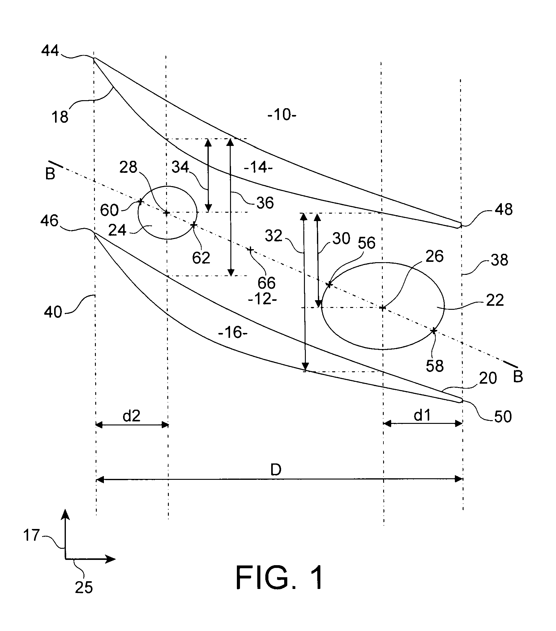
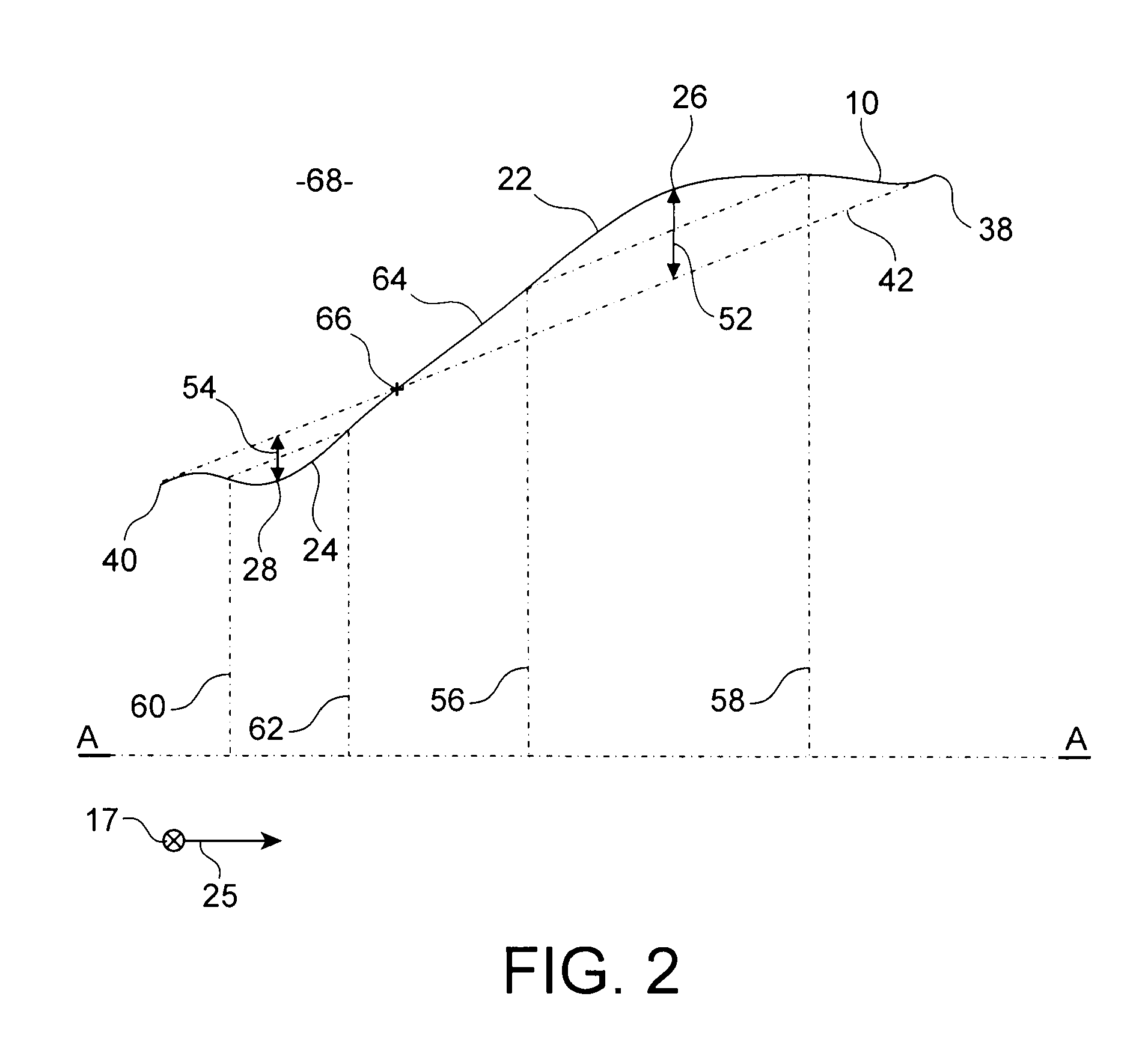
[0006]To this end it provides a rotor of a turbomachine compressor, including a rotor disk which holds blades each of which has an extrados surface and an intrados surface, where the disk is fitted, at its radially outer end, with a wall forming the inner end of an annular flow channel of a primary gas flow in the turbomachine, where this wall is formed from multiple angular sectors, each of which is delimited between the extrados surface of a first blade and the intrados surface of a second blade which follows the said first blade directly in a circumferential direction, where each of the said sectors includes a bulging portion which is convex in the axial direction and in the circumferential direction and has an apex located radially outside relative to an imaginary surface of revolution around the axis of the said rotor disk and passing through four points defined by the...


PUM


Abstract

A rotor of a turbomachine compressor, including a bladed rotor disk fitted at its radially external end with a wall forming the inner end of an annual flow channel of a primary gas flow, and formed from multiple angular sectors, each of which is delimited between two blades of the disk which are consecutive in a circumferential direction and includes a bulging portion which is convex in the axial direction and in the circumferential direction, together with, upstream from the bulging portion, a troughed portion which is concave in the axial direction and in the circumferential direction and which has a base which is roughly punctiform.

Description

TECHNICAL FIELD[0001]The present invention relates to turbomachine compressors, in particular for aircraft, and it concerns more specifically an inner end wall of an airstream of a primary gas flow in a rotor of such a compressor.STATE OF THE PRIOR ART[0002]A turbomachine compressor generally includes several successive compression stages, each of which is formed of a rotor comprising a bladed rotating disk, and a stator including an annular row of static blades intended to straighten and guide the gas flow flowing in the compressor.[0003]A problem is posed in the case of compressors in which the gas flow is supersonic relative to a radially external portion of certain blades, notably those of the rotor of the first stage of the compressor, i.e. of its most upstream compression stage, the radial extent of the portion of the blades operating at supersonic speed depending on the speed of displacement of these blades.[0004]The resulting supersonic shocks have an adverse effect on the e...

Claims


Application Information

Patent Timeline
IPC IPC(8): F01D5/02F01D5/14
CPCF01D5/143F04D29/321F04D29/329Y02T50/673F05D2250/712F05D2250/711F05D2240/80Y02T50/60
Inventor BOSTON, ERIC JACQUESCHARTOIRE, ALEXANDRE FRANCK ARNAUDILIOPOULOU, VASILIKILEPOT, INGRIDOBRECHT, THIERRY JEAN-JACQUES
Owner CENAERO
Why Eureka
Try Eureka