
Method for the Measurement and Analysis of Tyre Air Pressure with Allocation of Wheel Positions and System for Tyre Air Pressure Measurement

a technology of air pressure measurement and tyre, which is applied in the direction of vehicle position/course/altitude control, process and machine control, instruments, etc., can solve the problem that the allocation of air pressure checking device of the corresponding wheel to a specific wheel position of the vehicle cannot be guaranteed, and the data transfer must be largely error-free. , the effect of high immunity to interferen

Active Publication Date: 2012-08-09
MAXIM INTEGRATED PROD INC
View PDF10 Cites 7 Cited by
  • Summary
  • Abstract
  • Description
  • Claims
  • Application Information

AI Technical Summary

Benefits of technology

[0009]The object of the present invention is therefore to provide a method for the measurement and analysis of tyre air pressure which allocates wheel positions of a vehicle for analysis in a system for tyre air pressure measurement, and a system for tyre air pressure measurement for carrying out the method, which is both simple and cost-effective in its construction as well as having a particularly high immunity to interference.
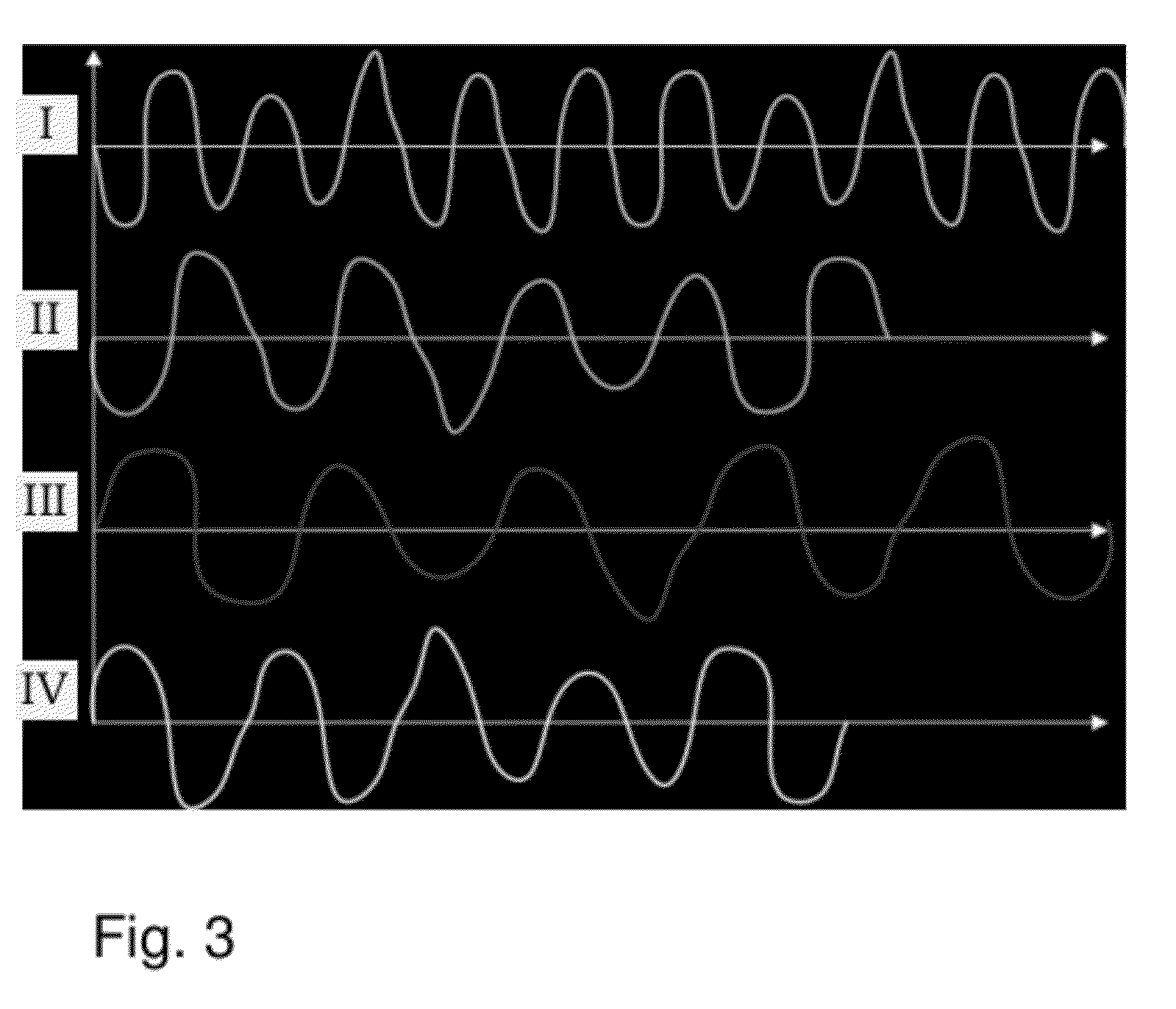
[0014]The term “low-frequency” is to be understood as a long wave in the lower wavelength range with corresponding frequencies between approximately 20 and 150 kilohertz. “Radio frequency” by contrast refers to frequencies greater than 100 Megahertz. Owing to the long wavelength of the low-frequency signals, practically no interference occurs, which means that detecting the periodicity of the wheel rotation is simpler and less error-prone. The transmission of the signals from the air pressure checking device of the wheel to the central unit of the vehicle on the other hand is carried out with radio-frequency signals, which allow better data transmission.
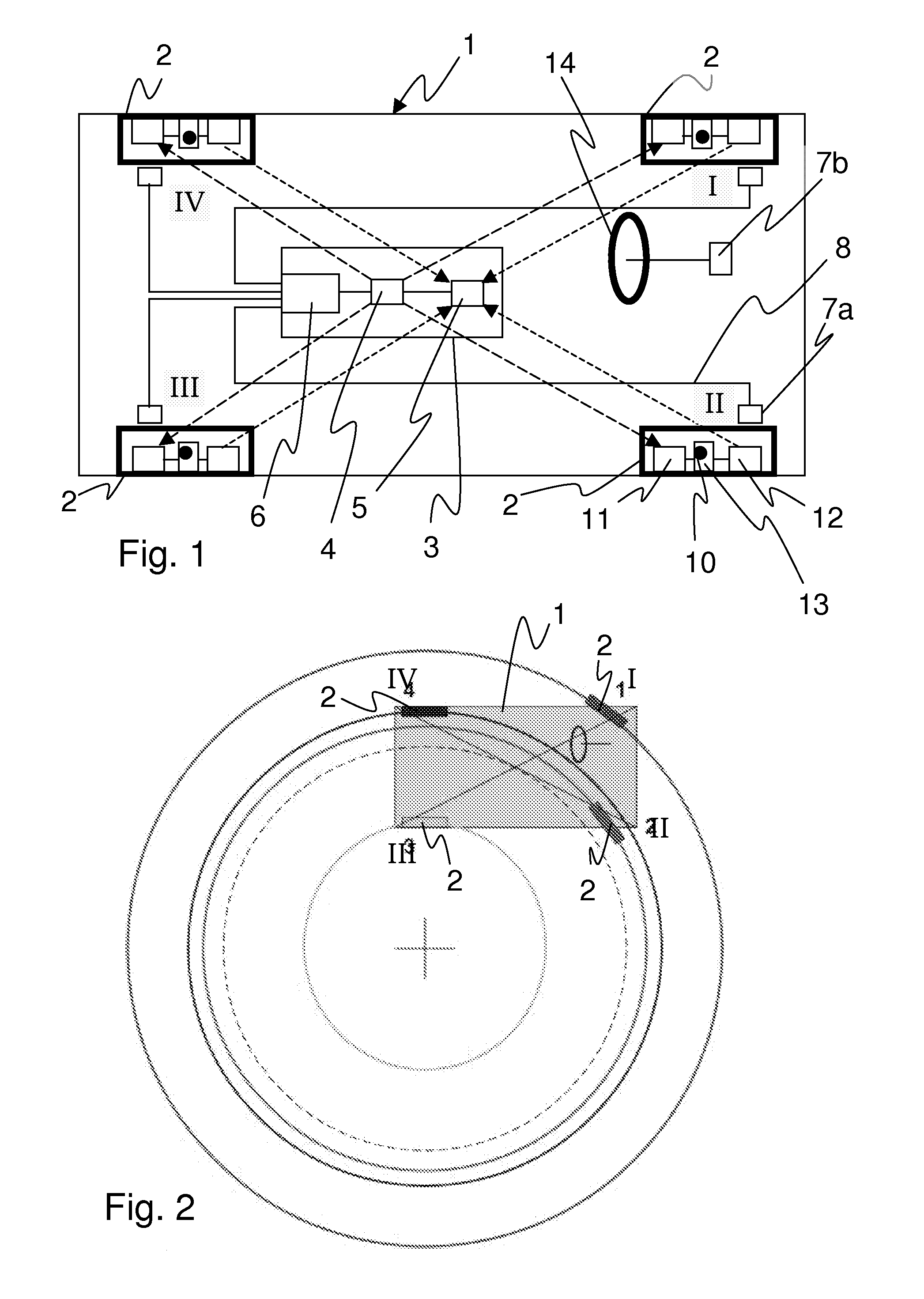
[0020]It is particularly advantageous if the allocation of the wheel position takes place while the vehicle is travelling around a bend. In particular when travelling around a bend, markedly different wheel rotation rates can be recorded on the vehicle. Due to this, the identification of the individual wheel rotation rates with the corresponding wheel positions is particularly easy to achieve.
[0023]To compare the wheel rotation rate determined by the frequency of the LF transmission and receiving devices with the wheel rotation rate of a known wheel position of the vehicle, in a particularly preferred embodiment the measurement device is provided in a stationary position on each wheel position for determining a wheel rotation rate there. The central unit communicates both with the RF transmission device on the wheel and also with the stationary measurement device, arranged at a known wheel position. From the data thereby obtained a comparison and thus an allocation of the signals from the wheel to a specific wheel position is facilitated. After this allocation an initialisation and / or synchronisation of the air pressure checking device takes place via the low-frequency transmission and receiver devices, and the transfer of the air pressure in the wheel determined by the air pressure checking device via the radio-frequency transmission and receiver devices.

Problems solved by technology

A problem with this arrangement, among other things, is that the data transfer must take place in a largely error-free manner.
Furthermore, a particular problem consists in the fact that the air pressure checking device may be allocated to a specific wheel position.
If this were not the case, the driver might not be informed about a problem at a specific wheel position.
If the wheel is changed however and eventually mounted at a different position on the vehicle, then the allocation of the air pressure checking device of the corresponding wheel to a specific wheel position of the vehicle cannot be guaranteed.
A disadvantage of this arrangement is that there is a relatively high cost for the cabling of the receivers and a corresponding sensitivity to interference.
A disadvantage of this arrangement is that the radio-frequency is susceptible to interference, since reflections from the surroundings can cause interference and signal dropout effects to occur.
This means it is difficult to determine a periodicity from the signals from which the rotation rate is derived.

Method used


Image

  • Method for the Measurement and Analysis of Tyre Air Pressure with Allocation of Wheel Positions and System for Tyre Air Pressure Measurement
  • Method for the Measurement and Analysis of Tyre Air Pressure with Allocation of Wheel Positions and System for Tyre Air Pressure Measurement
  • Method for the Measurement and Analysis of Tyre Air Pressure with Allocation of Wheel Positions and System for Tyre Air Pressure Measurement

Examples


Embodiment Construction

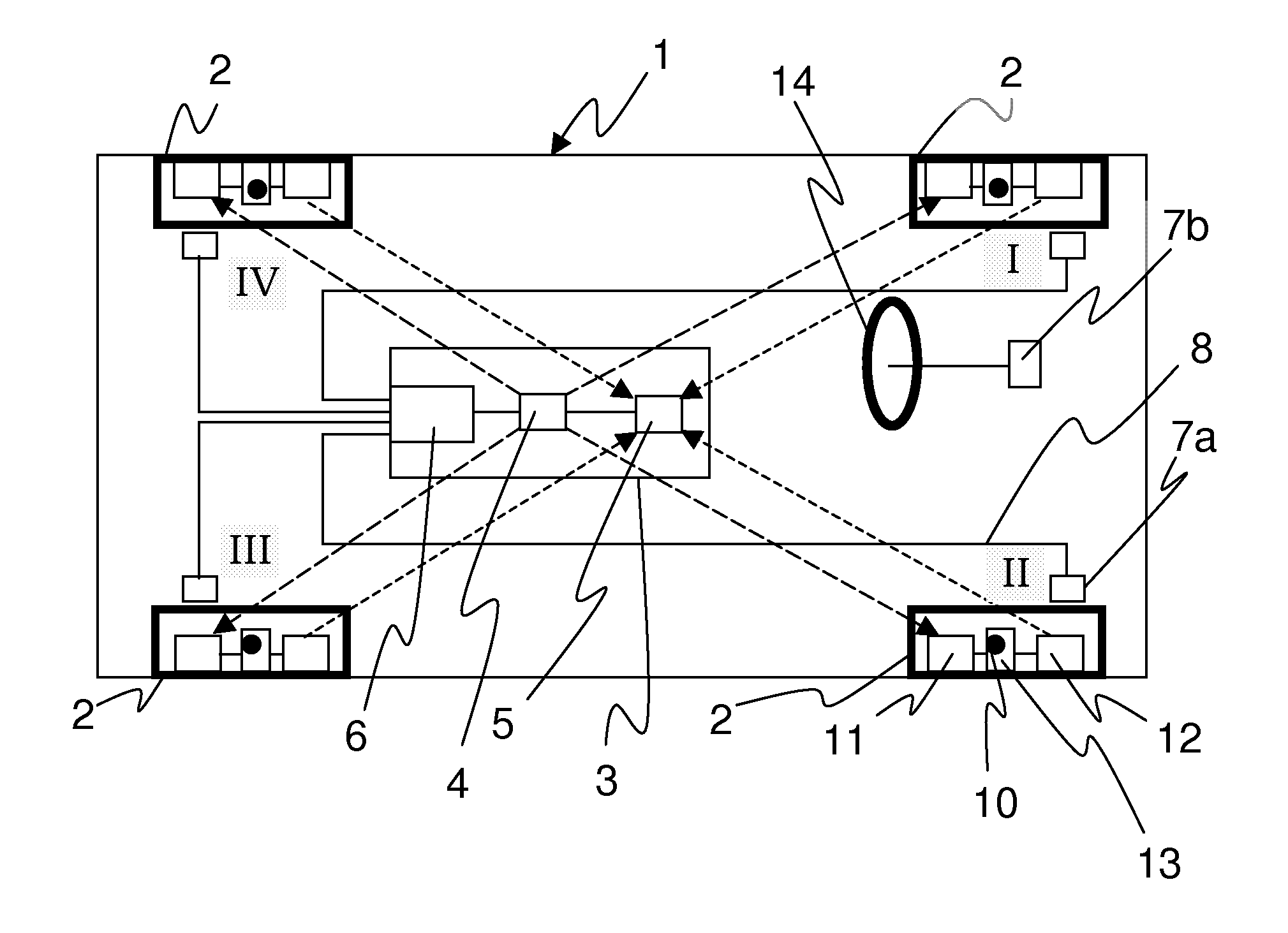
[0030]FIG. 1 shows a schematic illustration of a vehicle 1 with four wheels 2. In the vehicle 1 a central unit 3 is arranged, which contains a low-frequency LF transmitter 4 and a radio-frequency RF receiver 5. In addition the central unit 3 comprises a central analysis device 6. The central analysis device 6 has measurement devices 7a connected to it, here with a cable 8, which are arranged on each wheel 2 in a stationary position. The measurement device 7a determines the rotation rate of the respective wheel 2 allocated to it. It can be a component of a further monitoring system, such as an anti-lock braking system ABS or an electronic stability program ESP, for example.

[0031]An air pressure checking device 10 is located on each wheel 2. The air pressure checking device 10 consists of a pressure sensor, for example, which measures the internal pressure of the wheel. In addition, on each wheel 2 a low-frequency LF receiver 11 and a radio-frequency RF transmitter 12 are provided. Ai...


PUM


Abstract

In a method for the measurement and analysis of tyre air pressure with an allocation of wheel positions (I, II, III, IV) of a vehicle (1) for analysis in a tyre air pressure measurement system each wheel (2) of the vehicle (1) is allocated an air pressure checking device (10), an LF receiver (11), in particular a magnetic field strength receiver, an analysis unit (13), an RF-transmission device (12) and an individual wheel code. The LF receiver (11) receives electrical LF signals from an LF transmission device (4) of a central unit (3) arranged in the vehicle (1), the analysis unit (13) analyses the received signal amplitudes and from these determines a wheel rotation rate and the RF transmission device (12) of the wheel (2) sends RF signals with information about the wheel rotation rate and the individual wheel code to the central unit (3) of the vehicle (1). The central unit (3) determines the wheel position (I, II, III oder IV) of the wheel (2) using another measurement system (7) and allocates the air pressure checking device (10) and its individual wheel code to the known wheel position (I, II, III or IV) on the vehicle (1). A tyre air pressure measurement system has a central unit (3) arranged in a vehicle (1) with an LF transmission device (4), an RF receiver device (5) and a central analysis device (6). An air pressure checking device (10) arranged on each wheel (2) of the vehicle (1), an LF receiver device (11), RF transmission device (12) and analysis unit (13) for determining a rotation rate using a periodically varying amplitude of the received LF signal, and a measurement system (7) for measuring the wheel rotation rate at each wheel (2) and / or for determining the type of bend are additionally provided.

Description

CROSS REFERENCE TO RELATED APPLICATIONS[0001]This application is the National Phase Application under 35 USC §371 of International Application No. PCT / EP2010 / 065187, filed Oct. 11, 2010, which claims priority to German Patent Application 10 2010 000 919.9, filed Jan. 14, 2010, which claims priority to German Patent Application 10 2009 045 712.7, filed Oct. 14, 2009.BACKGROUND[0002]A. Technical Field[0003]The present invention relates to a method for the measurement and analysis of tyre air pressure with an allocation of wheel positions of a vehicle to be analysed in a system for tyre air pressure measurement, and a corresponding system for tyre air pressure measurement for carrying out the method.[0004]B. Background of the Invention[0005]Modern vehicles have tyre air pressure monitoring systems which determine the current tyre air pressure and warn the driver if a deviation occurs from a predetermined tyre air pressure. Tyre air pressure monitoring systems of this kind contribute co...

Claims


Application Information

Patent Timeline
Patent Type & Authority Applications(United States)
IPC IPC(8): B60C23/04
CPCB60C23/045B60C23/0416
Inventor SCHULTES, GERHARD
Owner MAXIM INTEGRATED PROD INC
Learn More