
Abnormality diagnostic device for vehicle and abnormality diagnostic method for vehicle

a technology for abnormality detection and vehicle, which is applied in the direction of electric devices, process and machine control, instruments, etc., can solve the problems of unnecessary trouble for drivers, adverse effects on vehicle performance, and decrepit fuel consumption, so as to prevent unnecessary replacement of parts during repair and increase the accuracy of failure detection in the temperature sensor provided at the rear-wheel drive motor.

Inactive Publication Date: 2012-08-09
TOYOTA JIDOSHA KK
View PDF14 Cites 17 Cited by
  • Summary
  • Abstract
  • Description
  • Claims
  • Application Information

AI Technical Summary

Benefits of technology

[0010]The invention provides a vehicle having a rear-wheel drive motor in which the accuracy of failure detection in a temperature sensor provided at the rear-wheel drive motor is increased.
[0013]According to the above-described aspects of the invention, the accuracy of failure detection in a temperature sensor provided at the rear-wheel drive motor is increased. Therefore, the driver may be prevented from being put unnecessarily to trouble and unnecessary replacement of parts during the repair may be prevented.

Problems solved by technology

Where temperature detection is impossible, for example due to electric disconnection of such temperature sensors, the performance of vehicle is adversely affected, e.g., fuel consumption is degraded.
However, where the accuracy of disconnection detection is poor, erroneous detection occurs, the driver may be unnecessarily put to trouble, or unnecessary replacement of parts may be performed during the repair.
The problem associated with the occurrence of erroneous detection in temperature sensors in the vehicles of such a configuration and techniques for preventing such erroneous defection have not been disclosed in JP-A-10-61479.

Method used


Image

  • Abnormality diagnostic device for vehicle and abnormality diagnostic method for vehicle
  • Abnormality diagnostic device for vehicle and abnormality diagnostic method for vehicle
  • Abnormality diagnostic device for vehicle and abnormality diagnostic method for vehicle

Examples


Embodiment Construction

[0021]An embodiment of the invention will be explained below in greater detail with reference to the appended drawings. In the drawings, like or corresponding parts are assigned with like reference numerals and the redundant explanation thereof will be omitted.

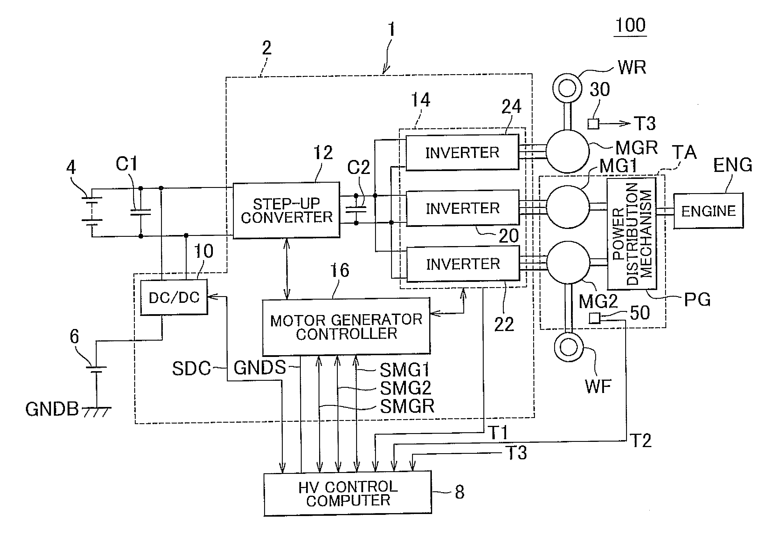
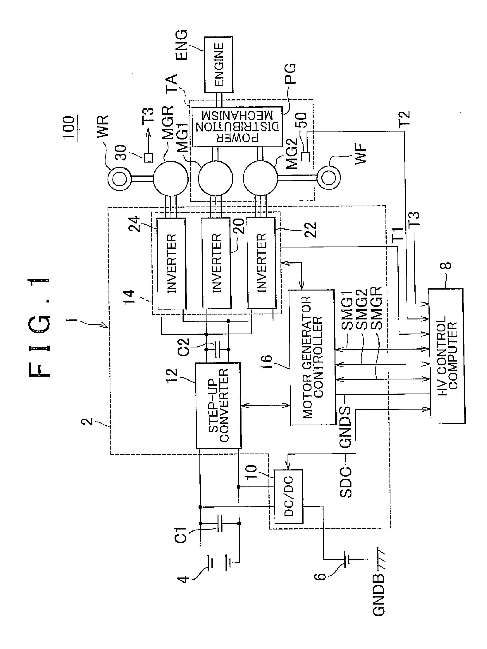
[0022]FIG. 1 is a block diagram illustrating the configuration of a vehicle 100 according to an embodiment of the invention.

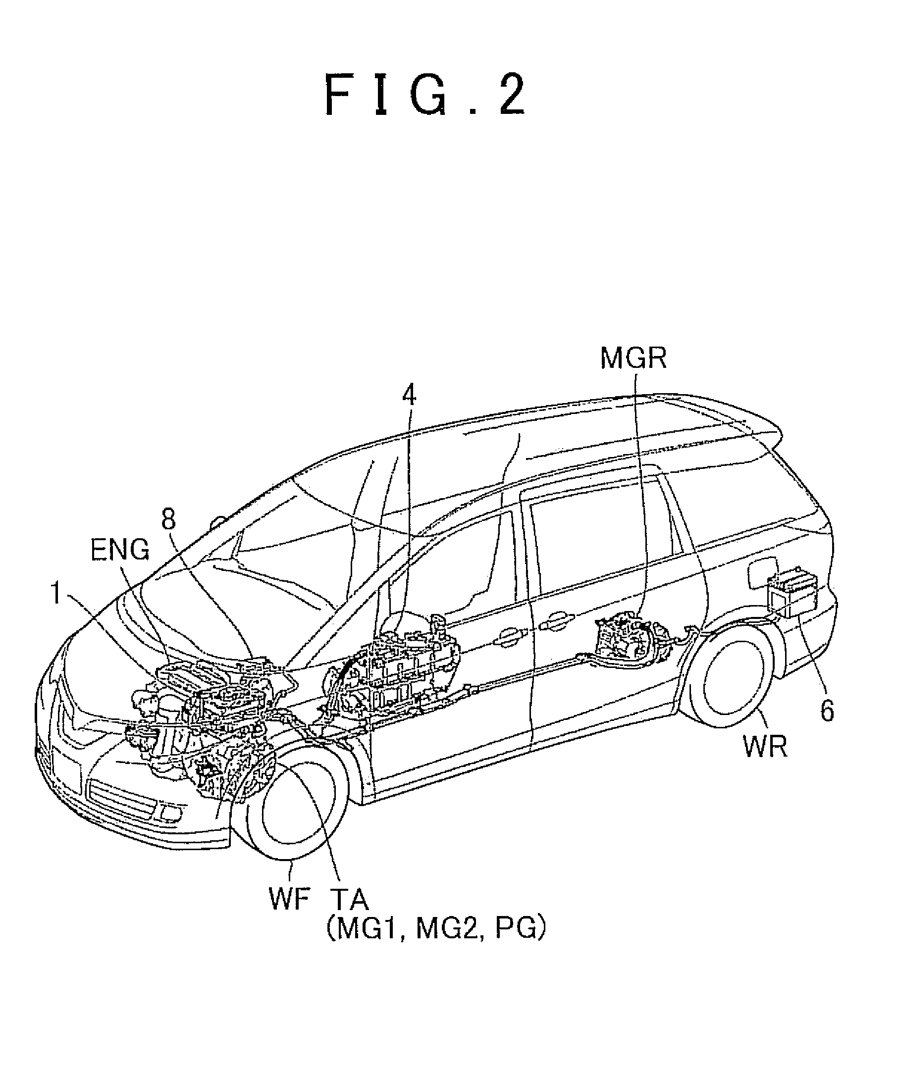
[0023]Referring to FIG. 1, the vehicle 100 is a hybrid automobile and includes a high-voltage battery 4, an auxiliary battery 6, a power control unit 1, a hybrid (HV) control computer 8, a transaxle TA, a motor generator MGR, an engine ENG, front wheels WF, and rear wheels WR. The transaxle TA includes motor generators MG1, MG2 and a power distribution mechanism PG.

[0024]The power distribution mechanism PG is coupled to the engine ENG and the motor generators MG1, MG2 and distributes the power therebetween. For example, a planetary gear mechanism having three rotating shafts of a sun gear, a planetary gea...


PUM


Abstract

An abnormality diagnostic device for a vehicle is provided with a first temperature sensor that detects the temperature of a rear-wheel drive motor, and a HV control computer that monitors the temperature of the rear-wheel drive motor by using the first temperature sensor and controls the rear-wheel drive motor. When a vehicle state satisfies a provisional determination condition indicating a connection abnormality of the first temperature sensor, the HV control computer performs verification processing of raising the temperature of the rear-wheel drive motor and verifying whether a detection value of the first temperature sensor demonstrates a predetermined variation, and establishes diagnosis of the connection abnormality on the basis of a result of the verification processing.

Description

INCORPORATION BY REFERENCE[0001]The disclosure of Japanese Patent Application No. 2011-023978 filed on Feb. 7, 2011 including the specification, drawings and abstract is incorporated herein by reference in its entirety.BACKGROUND OF THE INVENTION[0002]1. Field of the Invention[0003]The invention relates to an abnormality detection device for a vehicle and an abnormality detection method for a vehicle, and more particularly to an abnormality detection device and an abnormality detection method relating to a temperature sensor.[0004]2. Description of Related Art[0005]A variety of temperature sensors that detect temperature, such as an air temperature sensor, are installed on a vehicle as disclosed in Japanese Patent Application Publication No. 10-61479 (JP-A-10-61479). Where temperature detection is impossible, for example due to electric disconnection of such temperature sensors, the performance of vehicle is adversely affected, e.g., fuel consumption is degraded.[0006]Accordingly, e...

Claims


Application Information

Patent Timeline
Patent Type & Authority Applications(United States)
IPC IPC(8): G06F7/00
CPCB60L3/0061B60W2510/087B60W2050/0215B60W30/1843
Inventor MIGITA, TSUBASA
Owner TOYOTA JIDOSHA KK
Learn More