Drive control device for standby four-wheel drive vehicle

a four-wheel drive, control device technology, applied in vehicle position/course/altitude control, process and machine control, instruments, etc., can solve the problems and preventing the improvement of fuel economy. , to achieve the effect of reducing the regenerative efficiency of the motor generator, reducing the regenerative efficiency of the motor, and increasing the electric power consumed for operating the clutch devi

Inactive Publication Date: 2012-08-09
TOYOTA JIDOSHA KK
View PDF25 Cites 33 Cited by
  • Summary
  • Abstract
  • Description
  • Claims
  • Application Information

AI Technical Summary

Benefits of technology

[0004]In the conventional standby four-wheel drive vehicle, as described above, since the clutch device is operated such that the regenerative braking is performed with both the primary drive wheels and the secondary drive wheels during the regenerative braking of the motor generator, an amount of electric power consumed for operating the clutch device is increased and this is a factor that prevents improvement in fuel economy....

Problems solved by technology

In the conventional standby four-wheel drive vehicle, as described above, since the clutch device is operated such that the regenerative braking is performed with both the primary drive wheels and the secondary drive wheels during the regenerative braking of the motor generator, an amount of electric power consumed for operating the clutch device is increased and this is a factor that prevents improvement in fuel economy.
Si...

Method used


Image

  • Drive control device for standby four-wheel drive vehicle
  • Drive control device for standby four-wheel drive vehicle
  • Drive control device for standby four-wheel drive vehicle

Examples


first embodiment

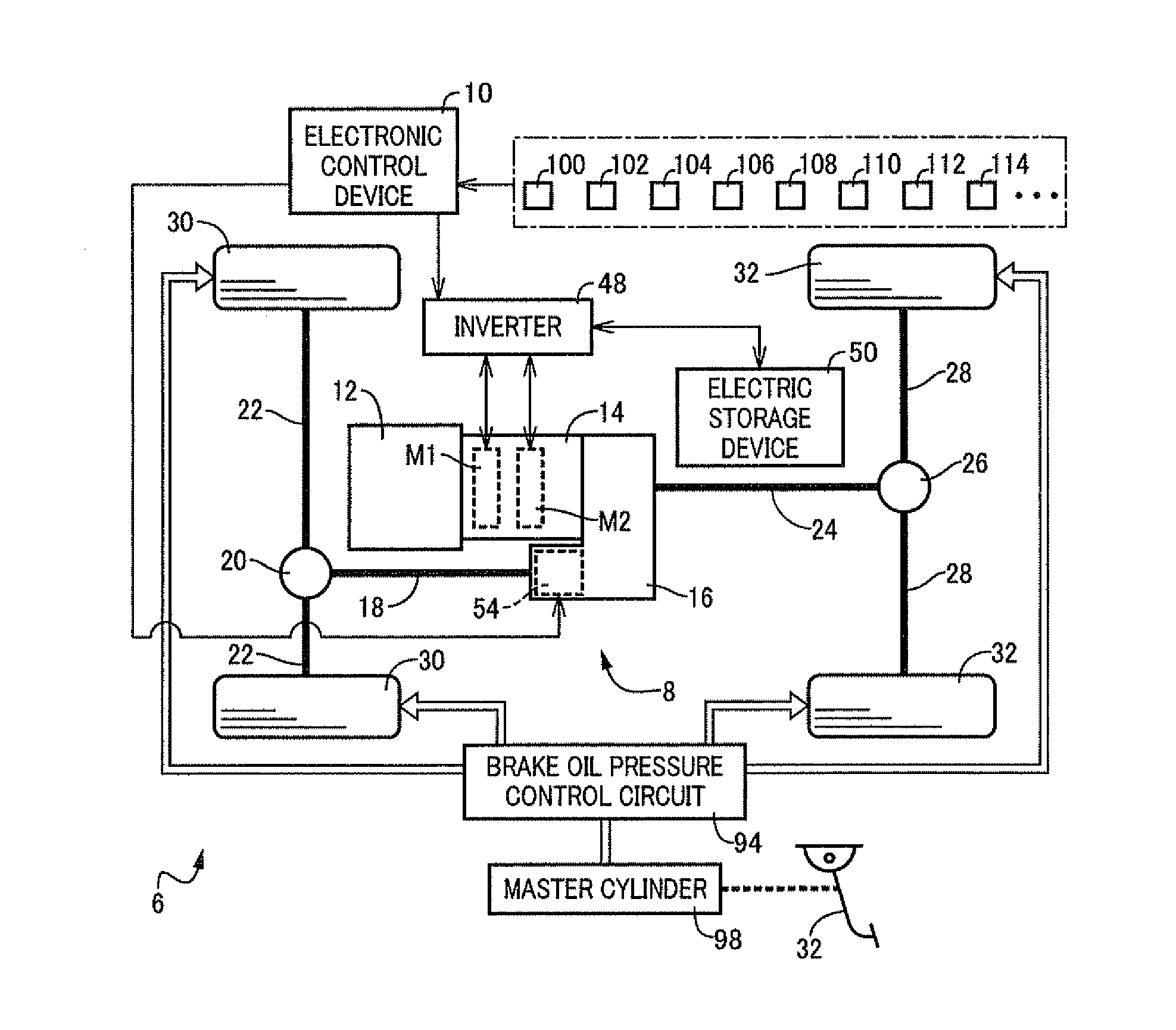
[0031]FIG. 1 is a diagram for explaining a vehicle driving device 8 and an electronic control device 10 for the control thereof disposed on a standby four-wheel drive vehicle 6 according to one embodiment of the present invention. The electronic control device 10 corresponds to a drive control device of the present invention. The vehicle driving device 8 of this embodiment is preferably used in a hybrid vehicle that employs a standby 4WD system based on a front-engine rear-drive system (FR).

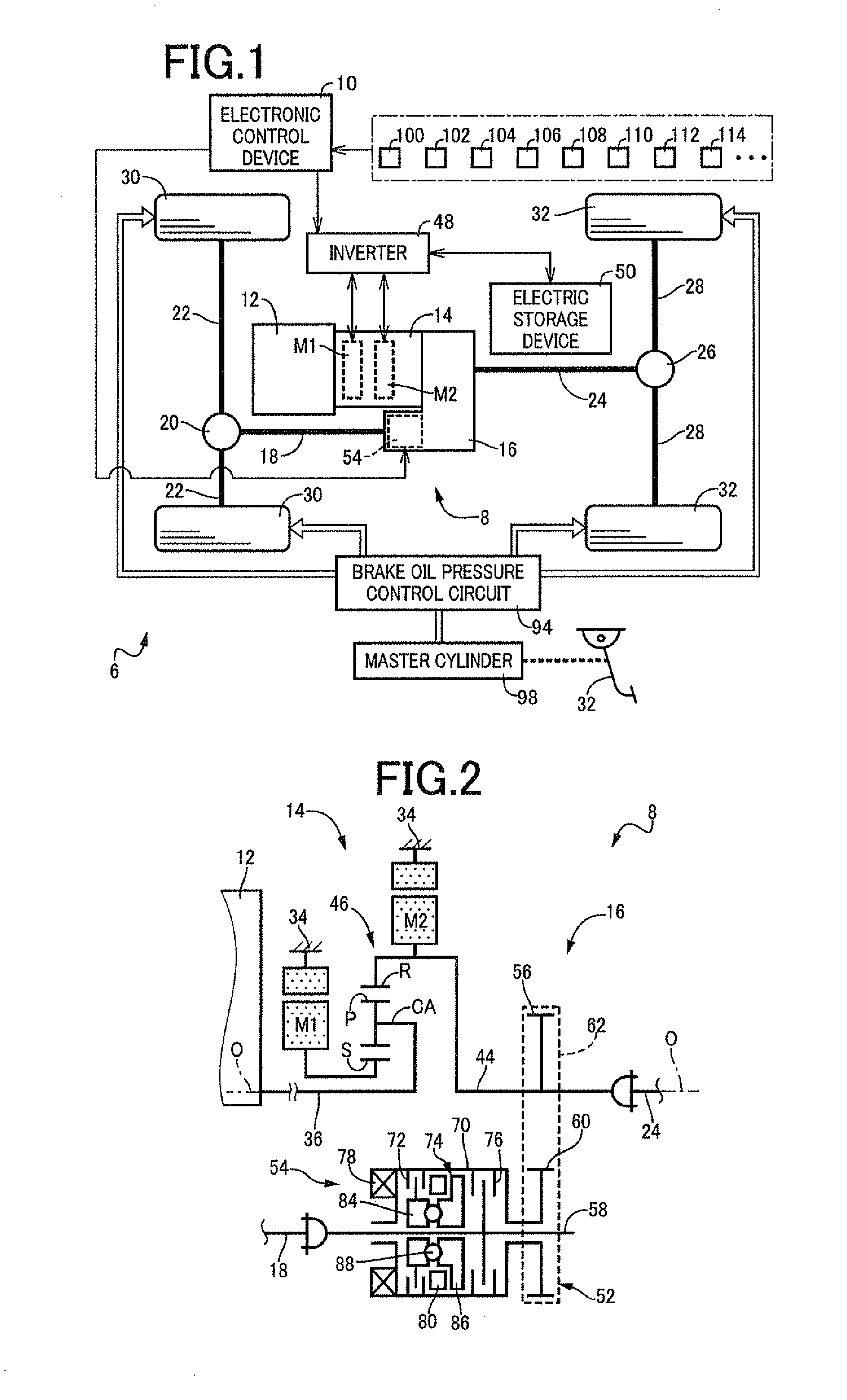
[0032]In FIG. 1, a drive force (drive torque) generated by an engine 12 is transmitted via a power transmission device 14 described later to a transfer 16. The drive force transmitted to the transfer 16 is distributed to a front propeller shaft 18 and a rear propeller shaft 24. The drive force transmitted to the front propeller shaft 18 is transmitted via a front-wheel differential gear device 20 and front-wheel axles 22 to a pair of left and right front-side drive wheels (front drive wheels) 30....

second embodiment

[0076]Another embodiment of the present invention will be described. In the following description of the embodiment, the portions overlapped with the embodiment described above will be denoted by the same reference numerals and will not be described.

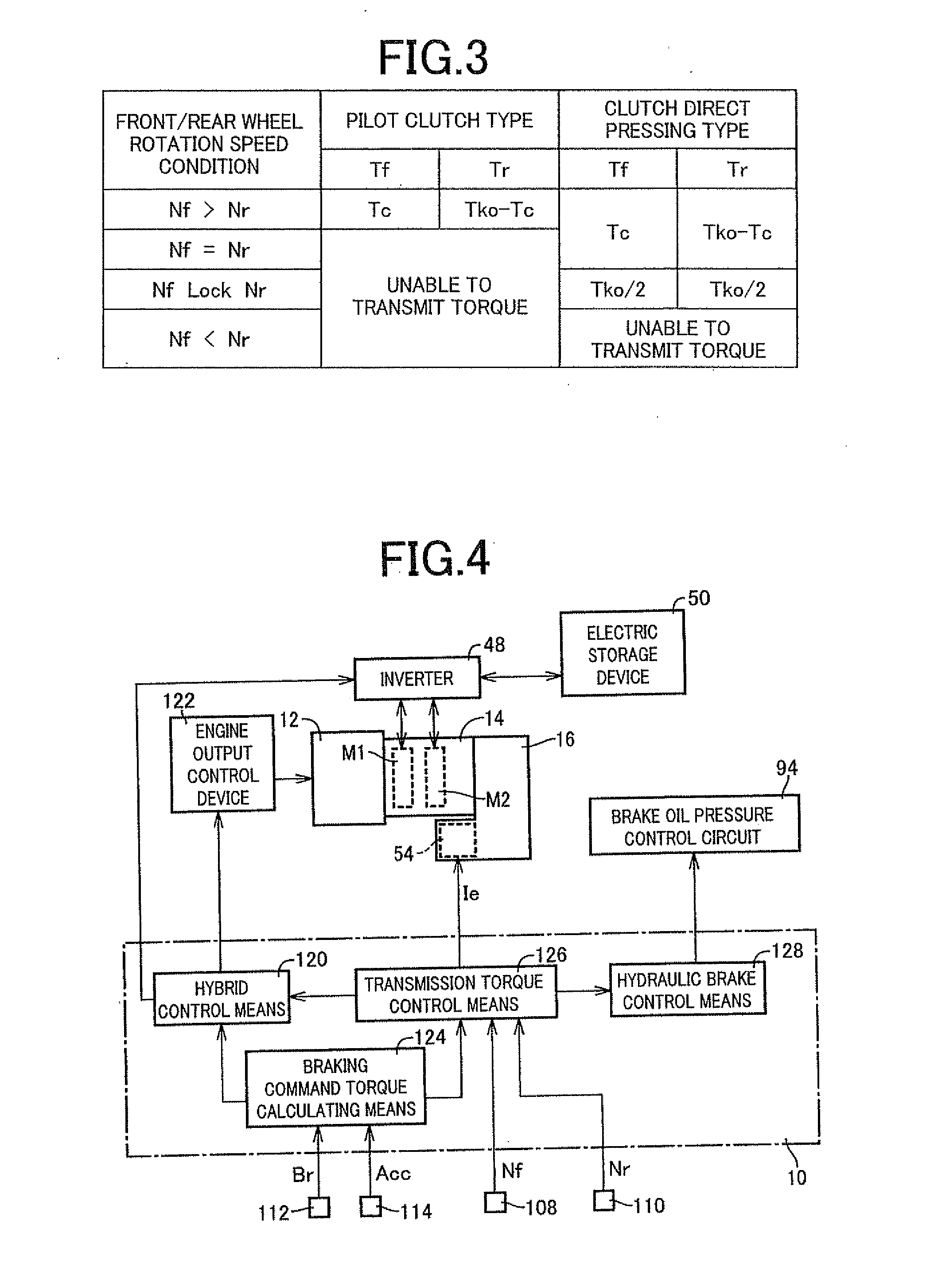
[0077]In FIG. 4, when determining whether the value acquired by subtracting the predetermined differential rotation number correction value k1 from the front-wheel rotation speed Nf exceeds the rear-wheel rotation speed Nr, if the determination is negative, the transmission torque control means 126 of this embodiment fixes the control coupling torque Tc of the control coupling device 54 to a value when the above determination is affirmative so as to increase the rear-wheel regenerative braking torque Tr. When the determination is negative and control coupling torque Tc is fixed to a given value, the transmission torque control means 126 determines whether the regenerative braking command torque Tko exceeds the regeneration limit torque T...

third embodiment

[0093]In FIG. 4, when determining whether the value acquired by subtracting the differential rotation number correction value k1 from the front-wheel rotation speed Nf exceeds the rear-wheel rotation speed Nr, if the determination is affirmative, the transmission torque control means 126 of this embodiment calculates respective loads acting on the front-side drive wheels 30 and the rear-side drive wheels 32, i.e., a front-wheel affecting load Ff and a rear-wheel affecting load Fr, based on a deceleration G of the vehicle supplied from the acceleration sensor in accordance with a relationship stored in advance, i.e., the following Equations (1) to (3). In the following Equations (1) to (3), Wf is a load acting on the front-side drive wheels 30 when the standby four-wheel drive vehicle 6 remains still on a level road surface, i.e., a static front-wheel load. Wr is a load acting on the rear-side drive wheels 30 when the standby four-wheel drive vehicle 6 remains still on a level road s...


PUM


Abstract

Provided is a drive control device for a standby four-wheel drive vehicle having primary drive wheels coupled to a drive source including a motor generator that generates a regenerative braking torque and a clutch device disposed between the drive source and secondary drive wheels to switch a two-wheel drive state using the primary drive wheels and a four-wheel drive state using the primary drive wheels and the secondary drive wheels, including: a transmission torque control portion that causes the clutch device to set a transmission torque between the drive source and the secondary drive wheels to zero so as to allow only the primary drive wheels to perform regenerative braking if a request braking torque of the vehicle is equal to or lower than a predetermined primary-drive-wheel regeneration limit torque during the regenerative braking by the motor generator, the transmission torque control portion causing the clutch device to generate the transmission torque between the drive source and the secondary drive wheels so as to allow the primary drive wheels and the secondary drive wheels to perform the regenerative braking if the request braking torque exceeds the primary-drive-wheel regeneration limit torque.

Description

TECHNICAL FIELD[0001]The present invention relates to a drive control device for a standby four-wheel drive vehicle, and, more particularly, to a technique of achieving a reduction in an amount of electric power consumed for operating a clutch device that switches a two-wheel drive state and a four-wheel drive state and an increase in a regenerative efficiency of a motor generator, thereby improving fuel economy.BACKGROUND ART[0002]A standby four-wheel drive vehicle is known that includes primary drive wheels coupled to a drive source including a motor generator that generates a regenerative braking torque, and a clutch device disposed between the drive source and secondary drive wheels to switch a two-wheel drive state using the primary drive wheels and a four-wheel drive state using the primary drive wheels and the secondary drive wheels. An example is a standby four-wheel drive vehicle of Patent Document 1, for example. In Patent Document 1, during regenerative braking by the mot...

Claims


Application Information

Patent Timeline
IPC IPC(8): B60L15/20B60L50/16B60W30/18
CPCB60K6/445Y02T10/6243B60L7/10B60L7/18B60L15/20B60L15/2045B60L15/2054B60L2260/26B60L2260/28B60W10/08B60W10/119B60W20/00B60W30/18127Y02T10/6239Y02T10/6265Y02T10/7283Y02T10/92B60K6/448B60K6/52Y02T10/62Y02T10/64Y02T10/72B60W20/13B60W10/18
Inventor YOSHIMURA, TAKAHIRO
Owner TOYOTA JIDOSHA KK
Why Eureka
Try Eureka