
Battery fuel gauge circuit

Active Publication Date: 2012-08-09
ROHM CO LTD
View PDF5 Cites 11 Cited by
  • Summary
  • Abstract
  • Description
  • Claims
  • Application Information

AI Technical Summary

Benefits of technology

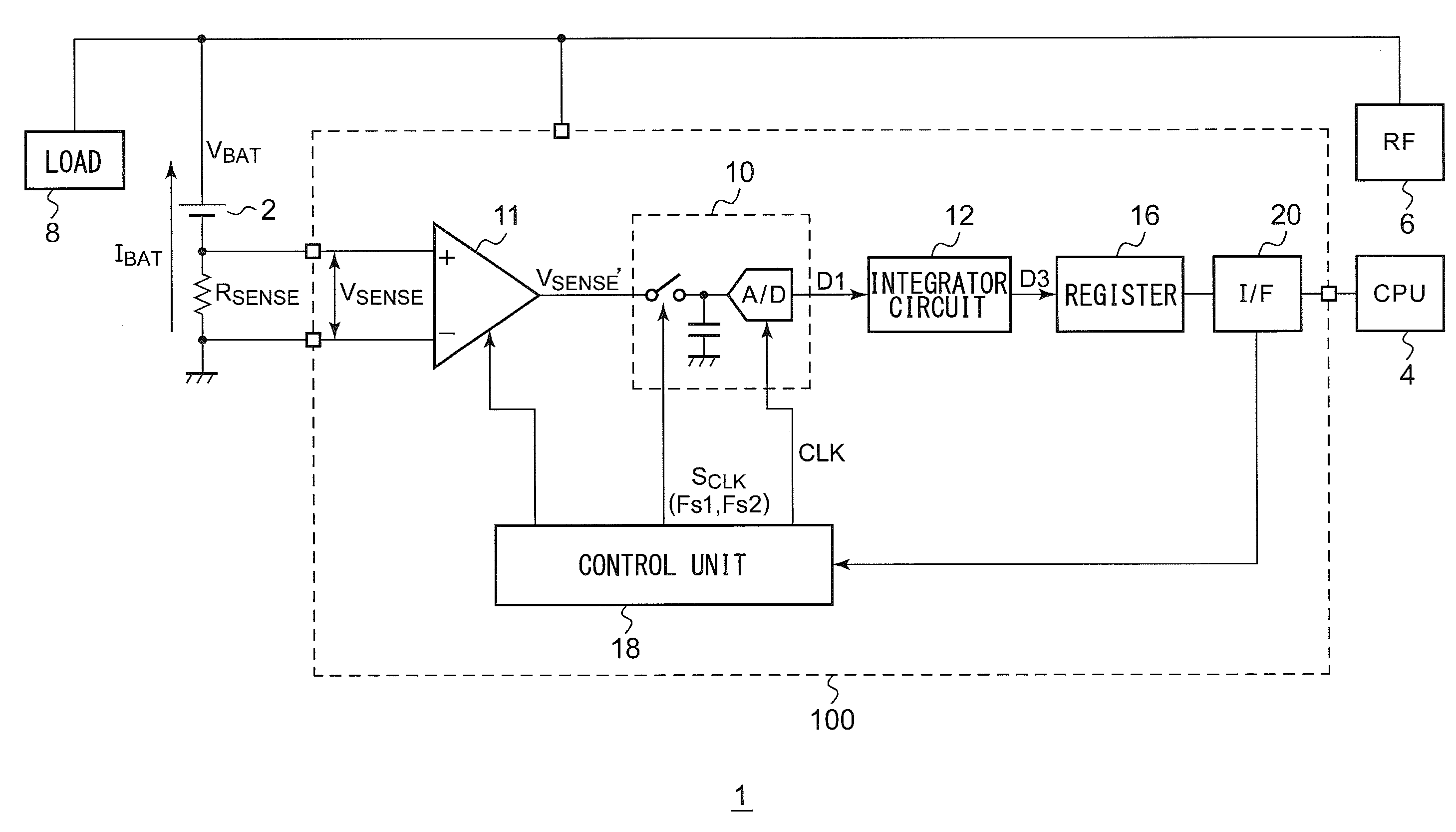
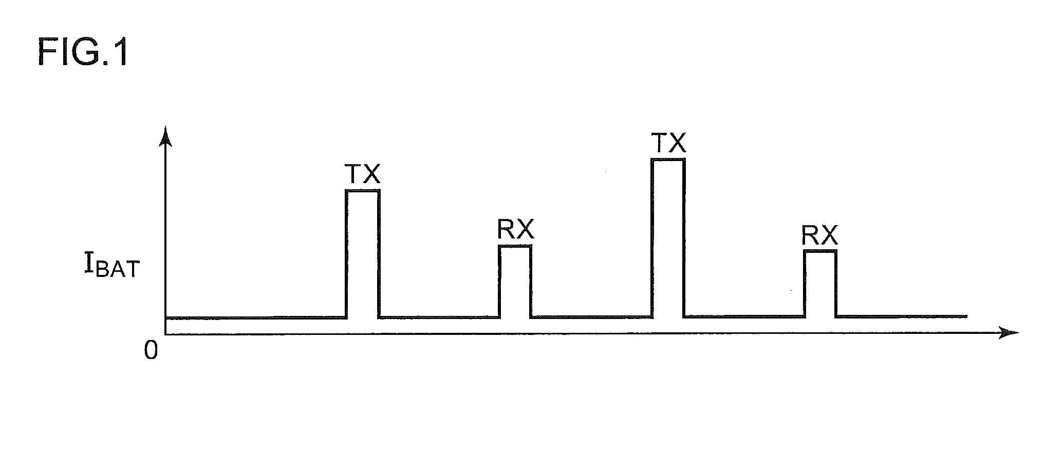
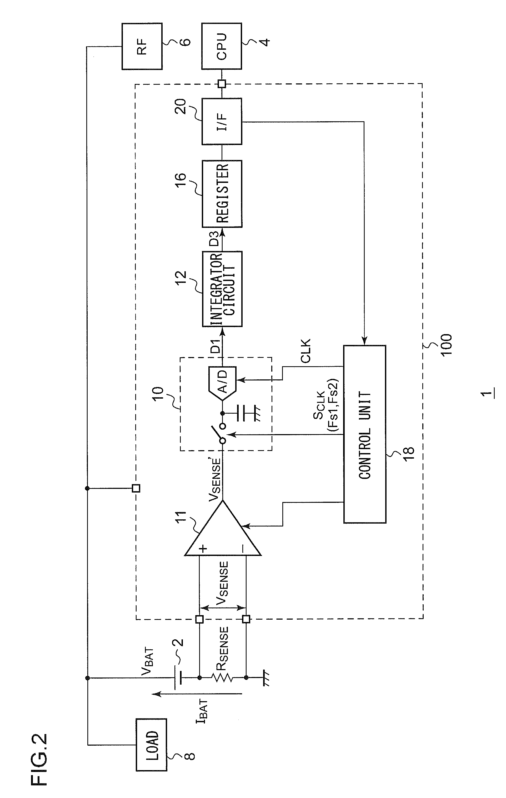
[0011]The processor has information with respect to the timing when each block mounted on the electronic device operates, i.e., the timing at which the battery current changes. Thus, by supplying, to the detection circuit, a control signal which indicates that there will be an increase in the current before a sharp increase occurs in the battery current, such an arrangement allows the detection circuit to sample such a sharp change in the current with an increased sampling frequency. Thus, such an arrangement provides improved detection precision. Furthermore, during a period in which the battery current stably exhibits a small value, the sampling operation is performed at a low sampling frequency, thereby suppressing an increase in power consumption.
[0013]In order to follow such a sharp change in the battery current, the amplifier is required to operate at a response speed that is increased to some extent. In order to raise the operation speed of the amplifier, there is a need to increase the operation current of the amplifier. With such an embodiment, such an arrangement requires the operation current to be increased only in the period in which the high-speed operation is to be performed. Thus, such an arrangement is capable of suppressing an increase in the total power consumption.
[0016]By providing the detection circuit with a function of integrating the current value and holding the integrated current value, such an arrangement does not require the processor to read out the current value with each sampling operation of the A / D converter. Thus, such an arrangement provides a reduced amount of calculation and a reduction in the number of times data transmission / reception is performed between the processor and the detection circuit, thereby providing reduced power consumption.

Problems solved by technology

However, such an increased sampling frequency leads to an increase in the power consumption of the battery fuel gauge circuit, which is undesirable.

Method used


Image

  • Battery fuel gauge circuit
  • Battery fuel gauge circuit
  • Battery fuel gauge circuit

Examples


Embodiment Construction

[0026]The invention will now be described based on preferred embodiments which do not intend to limit the scope of the present invention but exemplify the invention. All of the features and the combinations thereof described in the embodiment are not necessarily essential to the invention.

[0027]In the present specification, the state represented by the phrase “the member A is connected to the member B” includes a state in which the member A is indirectly connected to the member B via another member that does not substantially affect the electric connection therebetween, or that does not damage the functions or effects of the connection therebetween, in addition to a state in which the member A is physically and directly connected to the member B.

[0028]Similarly, the state represented by the phrase “the member C is provided between the member A and the member B” includes a state in which the member A is indirectly connected to the member C, or the member B is indirectly connected to ...


PUM


Abstract

A detection circuit is mounted on an electronic device having a communication function, including at least a battery, a CPU, and a communication unit, and is configured to detect the remaining battery charge. An A / D converter performs sampling of a magnitude of a current IBAT discharged from the battery, and converts the current IBAT thus sampled into a digital current value. An interface circuit receives, from the CPU, control data which indicates a period in which there is an increase in the current discharged from the battery. Based upon the control data, a control unit raises the sampling frequency of the A / D converter in the period in which there is an increase in the current IBAT.

Description

BACKGROUND OF THE INVENTION[0001]1. Field of the Invention[0002]The present invention relates to a battery fuel gauge circuit.[0003]2. Description of the Related Art[0004]Various kinds of battery-driven electronic devices such as cellular phone terminals, digital still cameras, PDAs (Personal Digital Assistants), laptop personal computers, etc., each include electronic circuits such as a CPU (Central Processing Unit) and a DSP (Digital Signal Processor), which are each configured to perform digital signal processing, a liquid crystal panel, other kinds of analog circuits and digital circuits, and so forth. Such electronic circuits are configured to operate receiving an electric power supply from a battery.[0005]Such an electronic device has a function of detecting the remaining battery charge by measuring a current (which will be referred to as the “battery current” hereafter) supplied from the battery to a load, and by integrating the current values thus measured. Such a function i...

Claims


Application Information

Patent Timeline
IPC IPC(8): G01R31/36
CPCG01R31/3613G01R31/3832H04W52/028Y02E60/10Y02D30/70H01M2010/4278
Inventor ANDO, KIMIOMATSUI, SHIGEKANEYAMAMOTO, ISAO
Owner ROHM CO LTD
Learn More