Exhaust manifold

a technology of exhaust manifold and manifold, which is applied in the direction of mechanical equipment, thermoelectric devices, machines/engines, etc., can solve the problems of particularly high thermal load on the exhaust manifold, achieve the effect of improving homogenous pressing, reducing the number of bending, and improving bending stiffness

Active Publication Date: 2012-08-16
PUREM GMBH
View PDF9 Cites 28 Cited by
  • Summary
  • Abstract
  • Description
  • Claims
  • Application Information

AI Technical Summary

Benefits of technology

[0007]The invention is based on the general idea of equipping the exhaust manifold with at least one thermoelectric converter. With the help of such a thermoelectric converter the temperature differential between the exhaust channel and the surroundings or a coolant channel can be utilised for generating an electric voltage and thus for generating electric energy. This produces a huge additional benefit for the cooled exhaust manifold, since electric energy can be won, in that a part of the heat carried along in the exhaust gas is converted into electric energy. Thus, through the introduced exhaust manifold, the energetic efficiency of the combustion engine equipped with such an exhaust manifold can be improved. In addition to this, the thermal load on the exhaust manifold is reduced through the attachment of the at least one thermoelectric converter, since a part of the heat is converted into electric energy. The advantages of an energy recovery in the form of a conversion of the heat into electric energy compared with a simple discharge of the heat via the cooling circuit are obvious. For example, the electric energy can be intermediate-stored and for example converted into drive energy in a particularly simple manner.
[0022]Additionally or alternatively it can be provided that the exhaust channel on its inside comprises at least one heat transfer structure for improving the heat transfer between exhaust gas channel and exhaust gas. Because of this, the effectiveness of the heat transfer and thus of the thermoelectric converters can be improved. Suitable heat transfer structures are for example turbulators, ribs, lamellae, baffle plates, fins and the like.

Problems solved by technology

Through the arrangement of the exhaust manifold directly on the combustion engine, the exhaust manifold is exposed to a particularly high thermal load.

Method used


Image

  • Exhaust manifold
  • Exhaust manifold
  • Exhaust manifold

Examples


Embodiment Construction

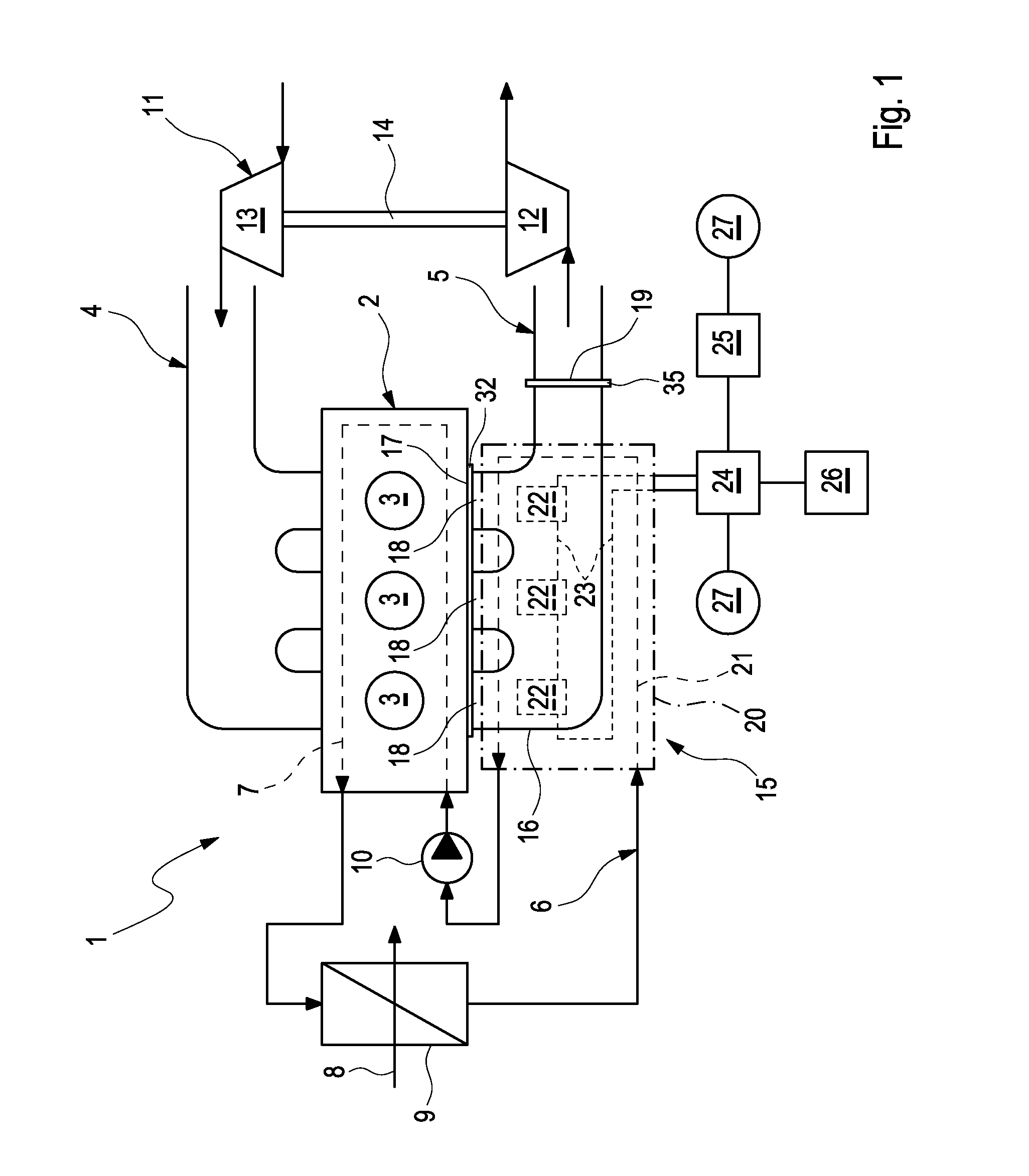
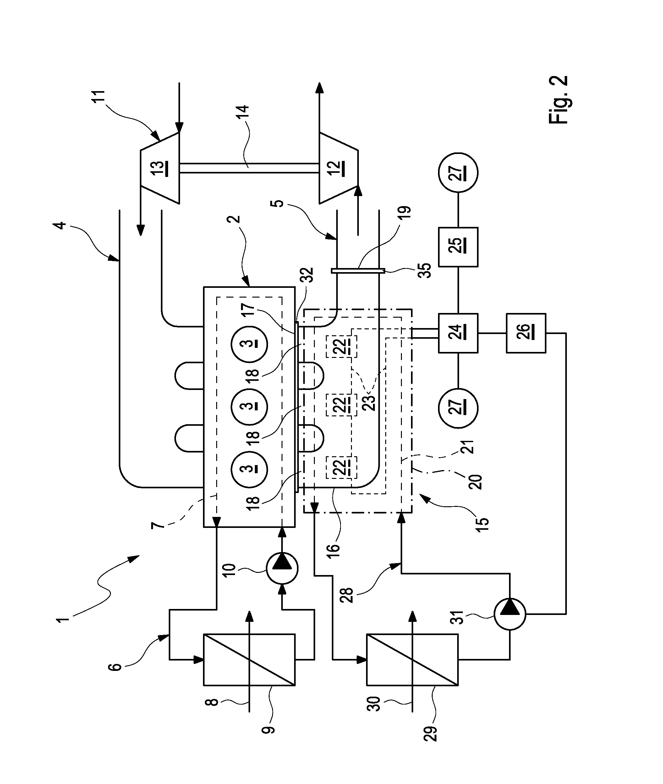
[0040]According to FIGS. 1 and 2, a combustion engine 1 comprises an engine block 2 with a plurality of cylinders 3, a fresh air system 4 for feeding fresh air to the cylinders 3 and an exhaust system 5 for discharging exhaust gas from the cylinders 3. The combustion engine 1 furthermore is equipped with a cooling circuit 6, which comprises at least one cooling path 7 routed the engine block 2, a radiator 9 exposed to a cooling air flow 8 and a pump 10 for driving the coolant.

[0041]In the shown example, the combustion engine 1 is additionally equipped with an exhaust gas turbocharger 11 whose turbine 12 is incorporated in the exhaust system 5, whose compressor 13 is incorporated in the fresh air system 4 and whose shaft 14 connects a turbine wheel of the turbine 12 with a compressor wheel of the compressor 13 which is not shown in a rotationally fixed manner.

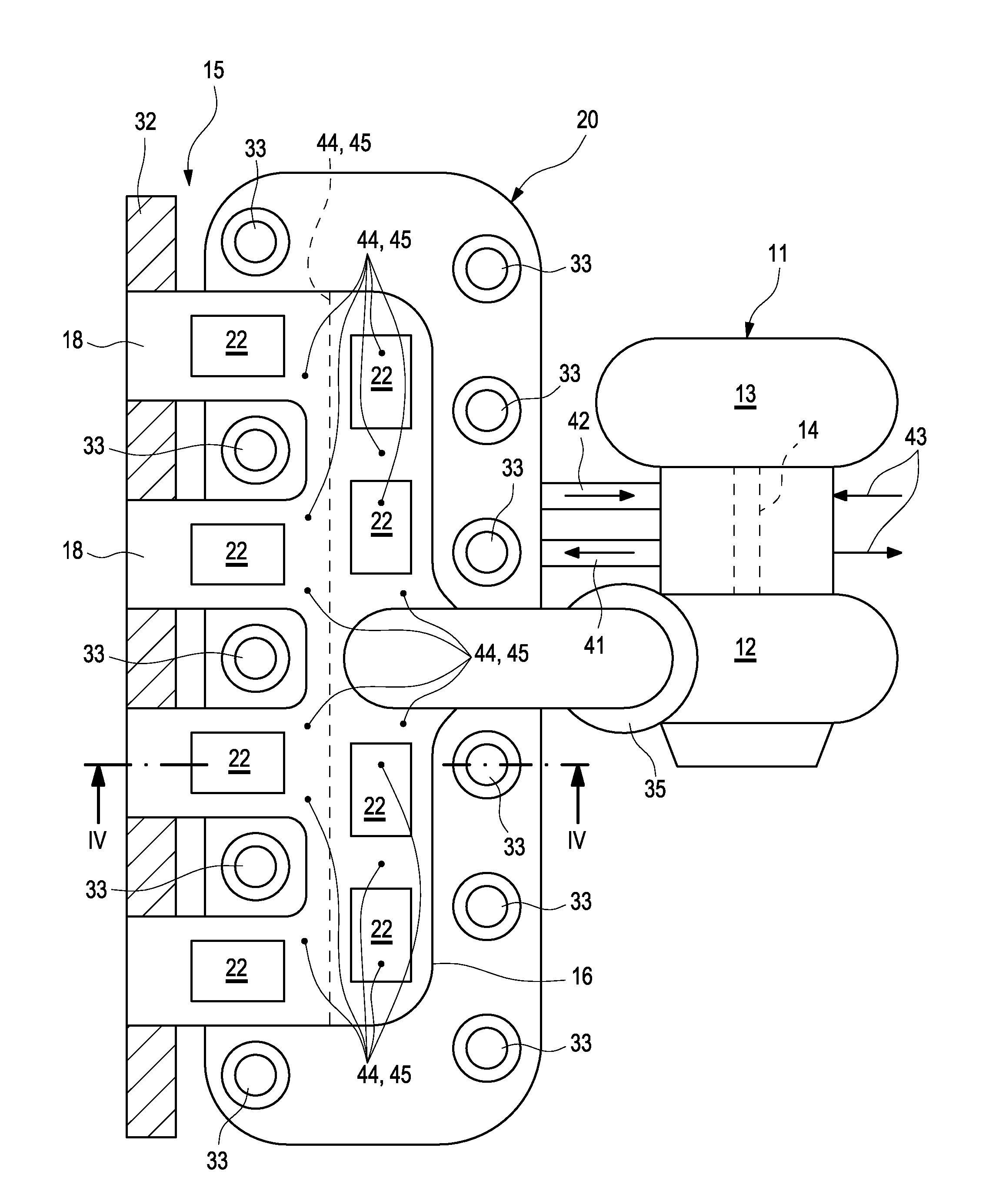
[0042]The exhaust system 5 is connected to the engine block 2 via an exhaust manifold 15. The exhaust manifold 15 according to...


PUM


Abstract

The present invention relates to an exhaust manifold (15) for an exhaust system (5) of a combustion engine (1), in particular of a motor vehicle, with an exhaust channel (16) for conducting exhaust gas, which comprises an inlet side (17) that can be connected to the combustion engine (1) and an outlet side (19) that can be connected to the exhaust system (5), and with at least one coolant channel (20) for conducting coolant, which is arranged on the outside of the exhaust channel (16) and can be connected to a cooling circuit (6).In order to reduce the thermal load on the exhaust manifold (15), at least one thermoelectric converter (22) can be provided, which on the one hand is coupled to the exhaust channel (16) and on the other hand to the coolant channel (20) in a heat-transferring manner.

Description

CROSS-REFERENCE TO RELATED PATENT APPLICATION[0001]This patent application claims priority to German Application No. 102011004243.1-13, filed Feb. 16, 2011, the entire teachings and disclosure of which are incorporated herein by reference thereto.FIELD OF THE INVENTION[0002]The present invention relates to an exhaust manifold for an exhaust system of a combustion engine, in particular of a motor vehicle. The invention additionally relates to a combustion engine equipped with at least one such exhaust manifold. Finally, the present invention additionally relates to a method for operating such a combustion engine.BACKGROUND OF THE INVENTION[0003]Exhaust manifolds are generally known and serve in combustion engines for collecting and combining the exhaust gases discharged from the cylinders of the combustion engine. Usually, such an exhaust manifold comprises an exhaust channel for conducting the exhaust gas which comprises an inlet side that can be connected to the combustion engine a...

Claims


Application Information

Patent Timeline
Patent Type & Authority Applications(United States)
IPC IPC(8): F01N5/02F01N13/10F02B33/44F01N3/02H01L35/30
CPCF01N13/10Y02T10/16F01N5/02H01L35/30F01N5/025Y02T10/166Y02T10/12H10N10/13
Inventor JEBASINSKI, ROLFWIRTH, GEORG
Owner PUREM GMBH
Why Eureka
Try Eureka