Folding table

Inactive Publication Date: 2012-08-16
SICO INC
View PDF13 Cites 6 Cited by
  • Summary
  • Abstract
  • Description
  • Claims
  • Application Information

AI Technical Summary

Benefits of technology

[0007]The present invention is directed to a folding table and in particular to a folding table having a single tabletop and a damper assembly to facilitate controlled folding between use and storage positions. The folding table includes two pairs of opposed legs with each pair having an associated framework. These assemblies are connected by a pair of folding linkages that facilitate folding between a use position and a storage position. In the use position, the single tabletop extends over the legs and framework in a substantially horizontal plane. In the storage position, the tabletop is substantially vertical. The storage position provides for a smaller footprint, requiring less storage space, allows a degree of nesting between adjacent tables and facilitates transportation between storage and use locations.
[0009]The framework includes pivoting members supporting the tabletop and connecting the legs. A pair of folding linkages have cross links that mount between the pairs of legs and facilitate the folding between the use position and the storage position. The folding tabletop is positioned slightly off center from the folding axis so that a majority of the tabletop is below the axis in the storage position. Such a position provides for a lower center of gravity and requires less effort from workers to fold and unfold the table.
[0010]In addition to the folding linkages, folding and unfolding the table is facilitated by a damper assembly including a damper having a damper body containing a damping fluid and a telescoping rod extending from the damper body. Valves in the damper control fluid into and out of the damper body and vary the damping forces so that damping engages at the proper position during folding and unfolding and provides the required forces needed while allowing the table to fold and unfold without requiring undue effort from a person folding and / or unfolding the table.
[0012]Folding and unfolding of the table is accomplished by gripping the tabletop at the ends or grasping handles on an underside of the tabletop proximate the top edge from the tabletop assembly storage position. Folding from the use position to the storage position is easily accomplished by simply lifting the tabletop upward and allowing the linkages to fold and using the weight of the tabletop to move to the storage position. The damper assembly also provides a mechanical force to aid in folding to the storage position.
[0013]Unfolding from the storage position to the use position is accomplished by again grasping the tabletop and guiding the tabletop downward toward the horizontal position. The tabletop is offset slightly and balanced so that the tabletop will fall somewhat slowly until reaching a position wherein the damper engages with greater force. This position might typically be, for example, at approximately 30 degrees from horizontal, after which the damper controls the speed of the table motion as the table top moves down to the horizontal position. It can be appreciated that no locks are required and that the folding may be easily performed with a single person guiding the tabletop between the storage and use positions. The valves in the damper provide uneven flow between extension and retraction of the telescoping rod to match the damping forces needed for folding and unfolding. The damper provides for faster motion when the tabletop is raised to the substantially vertical storage position than when being lowered to the substantially horizontal use position.
[0014]This configuration provides several advantages. When the table is in the use position, the damper extends vertically and the force extends through the pivot. Therefore, the force of the damper does not act so as to tend to fold the table. Moreover, the damper exerts a force that assists in maintaining the table in the storage position as the table is transported between storage and / or use locations.

Problems solved by technology

Although such tables provide great utility and increase the flexibility of spaces in which they are used, the tables do have some drawbacks.
Moreover, it may be difficult to maintain a slow controlled folding motion so that the tabletops do not slam down towards the use position.
Although such tables do provide a tabletop surface with great utility, the surface is not continuous.
The tabletop members folding along an adjacent edge may present a pinching hazard requiring workers to use care during folding and unfolding.

Method used


Image

  • Folding table
  • Folding table
  • Folding table

Examples


Embodiment Construction

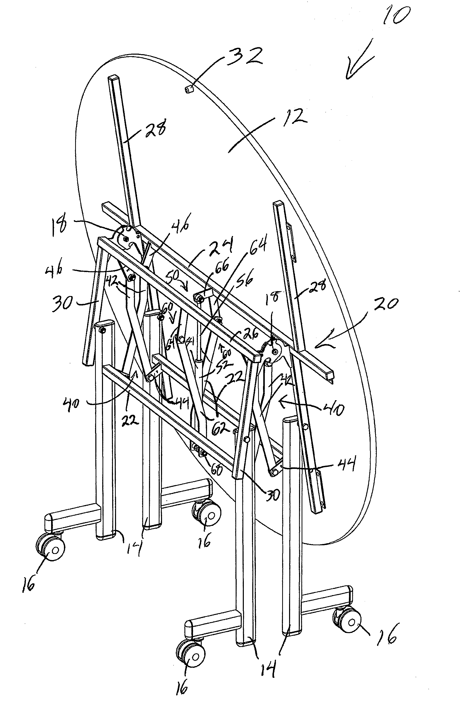
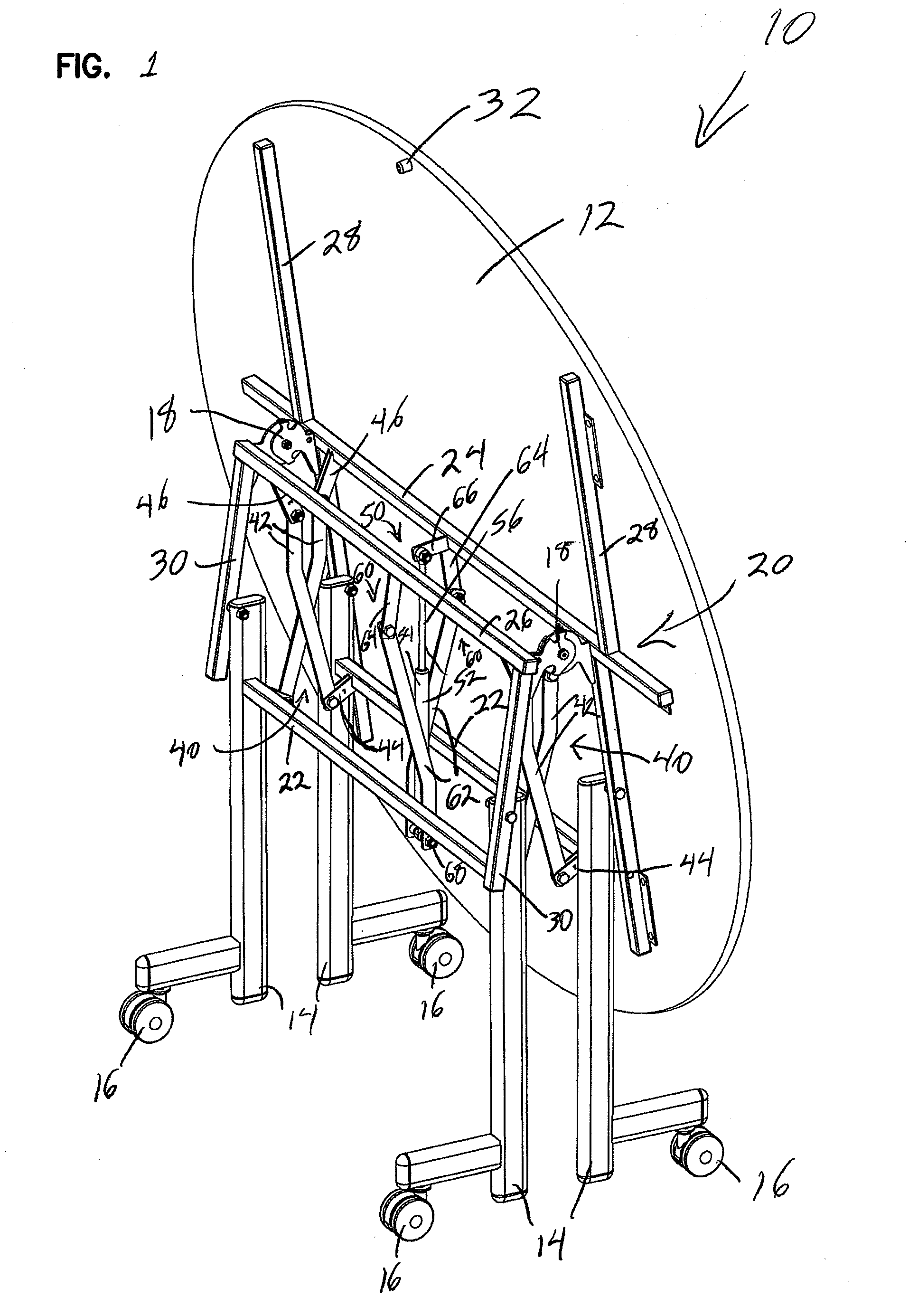
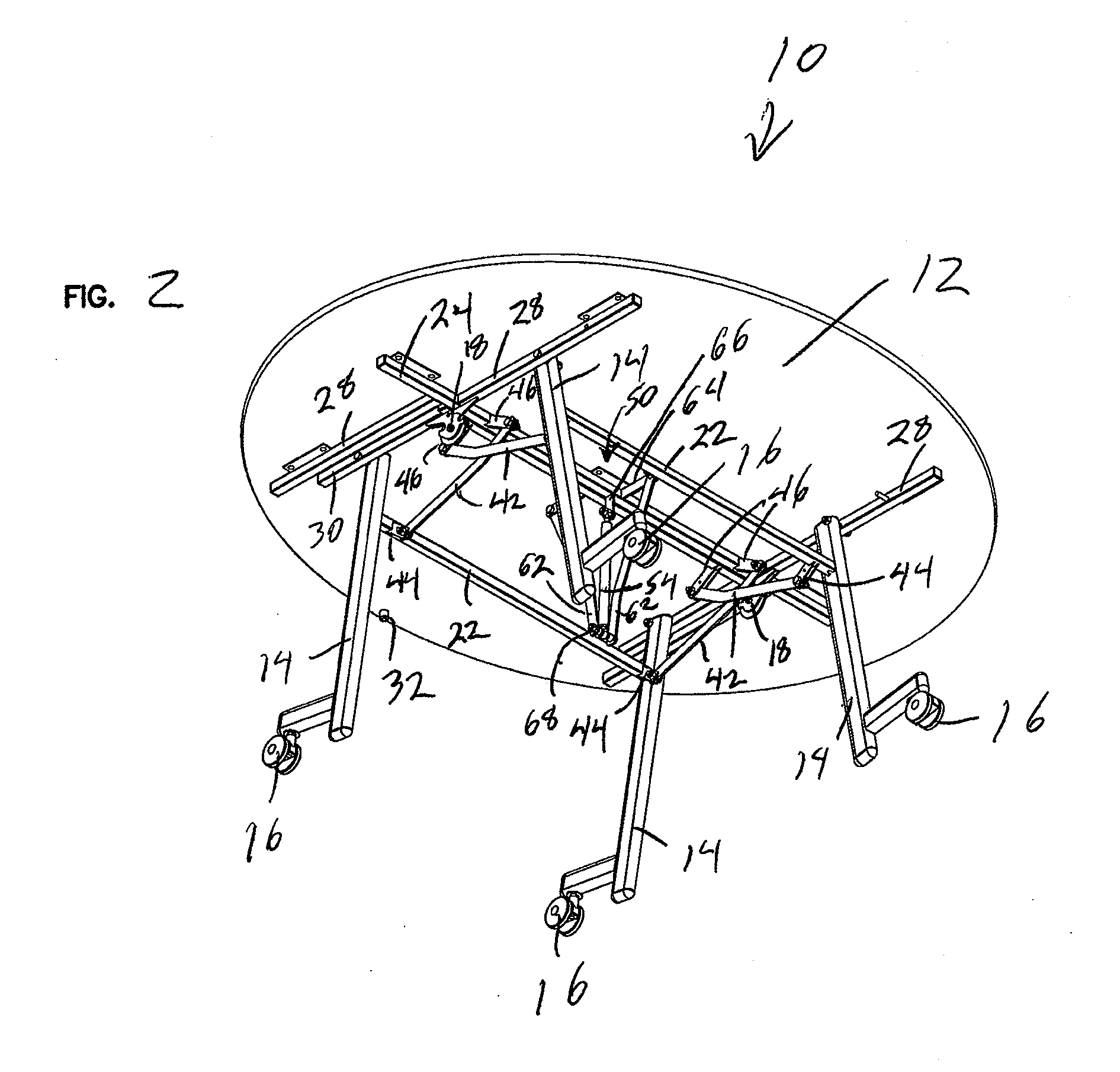
[0025]Referring now to the drawings and in particular to FIGS. 1 and 2, there is shown a portable folding table, generally designated 10. In the embodiment shown, the folding table 10 contains a single oval tabletop 12. However, other common tabletop shapes can also be used. The folding table 10 also includes legs 14 with casters 16 mounted on the legs 14. In the use position shown in FIG. 2, the table 10 is supported solely on the legs 14 while the casters 16 are lifted off the floor. Conversely, in the folded storage position shown in FIG. 1, the legs 14 are automatically lifted from the floor and the folding table 10 is supported solely on the casters 16, as shown most clearly in FIG. 4.

[0026]As shown most clearly in FIGS. 1, 3, 4 and 6, the folding table 10 includes a frame 20 pivotally mounted to the legs 14. The framework of each pair of legs 14 pivots about hinges 18 to define a folding axis for the table 10. A center frame member 24 mounts to an underside of the tabletop 12 ...


PUM


Abstract

A folding table includes a single tabletop extending over a framework and legs. The folding table includes a first framework with a first pair of legs and a second framework including a second pair of legs. Folding linkages fold the tabletop between a first use position wherein the tabletop is substantially horizontal and second storage position wherein the tabletop is substantially vertical. A damping assembly includes a damper mounted to the tabletop and the frameworks and includes a damping linkage to guide and provide controlled folding and unfolding of the table.

Description

BACKGROUND OF THE INVENTION[0001]1. Field of the Invention[0002]The present invention relates to a folding table and in particular to a portable folding table having a single folding tabletop member.[0003]2. Description of the Prior Art[0004]Folding tables are widely used in rooms that are used for multiple purposes. Tables can be rapidly set up in a room, and then quickly folded and put in storage as may be required. A typical prior art folding table has a pair of tabletop surfaces that are hingedly connected along adjacent edges. Leg assemblies pivotally connect to the undersides of the tabletops and cross connect links pivotally interconnect the legs of one tabletop surface to the underside of the opposite tabletop surface. With such a configuration, tables fold between a substantially vertical storage position wherein the tabletop members and legs are generally vertically oriented and a horizontal use position wherein the tabletop surfaces are generally horizontal to define an e...

Claims


Application Information

Patent Timeline
IPC IPC(8): A47B3/00A47B13/02
CPCA47B2200/0036A47B3/002
Inventor ELLIOTT, JOHN M.DICKEY, CHRISTOPHER C.
Owner SICO INC
Why Eureka
Try Eureka