Internal power supply voltage generation circuit

a technology of voltage generation circuit and power supply voltage, which is applied in the direction of electric variable regulation, process and machine control, instruments, etc., can solve the problems of increasing current consumption and difficulty in maintaining the internal power supply voltage dvdd constant, and achieve the effect of suppressing current consumption and operating stably

Inactive Publication Date: 2012-08-16
SEIKO INSTR INC
View PDF21 Cites 5 Cited by
  • Summary
  • Abstract
  • Description
  • Claims
  • Application Information

AI Technical Summary

Benefits of technology

[0013]According to the present invention, the internal power supply voltage generation circuit can be provided, with which the through current can be prevented from being excessive due to manufacturing fluctuations during the operation of the logic circuit to which the internal power supply voltage is supplied, and current consumption can be suppressed as well.
[0014]Besides, the internal power supply voltage has no excessive voltage fluctuations during the operation of the logic circuit, and hence the logic circuit can operate stably.

Problems solved by technology

Accordingly, there has been a problem that it is difficult to maintain the internal power supply voltage DVDD constant.
For example, when the internal power supply voltage DVDD fluctuates to be higher, the through current becomes excessive during the operation of the logic circuit 802, and the current consumption increases.

Method used


Image

  • Internal power supply voltage generation circuit
  • Internal power supply voltage generation circuit
  • Internal power supply voltage generation circuit

Examples


Embodiment Construction

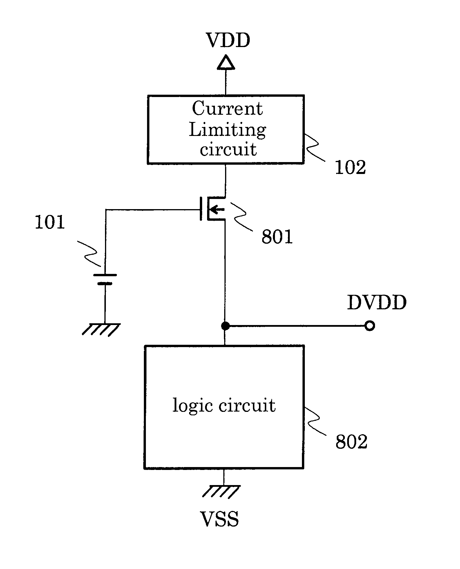
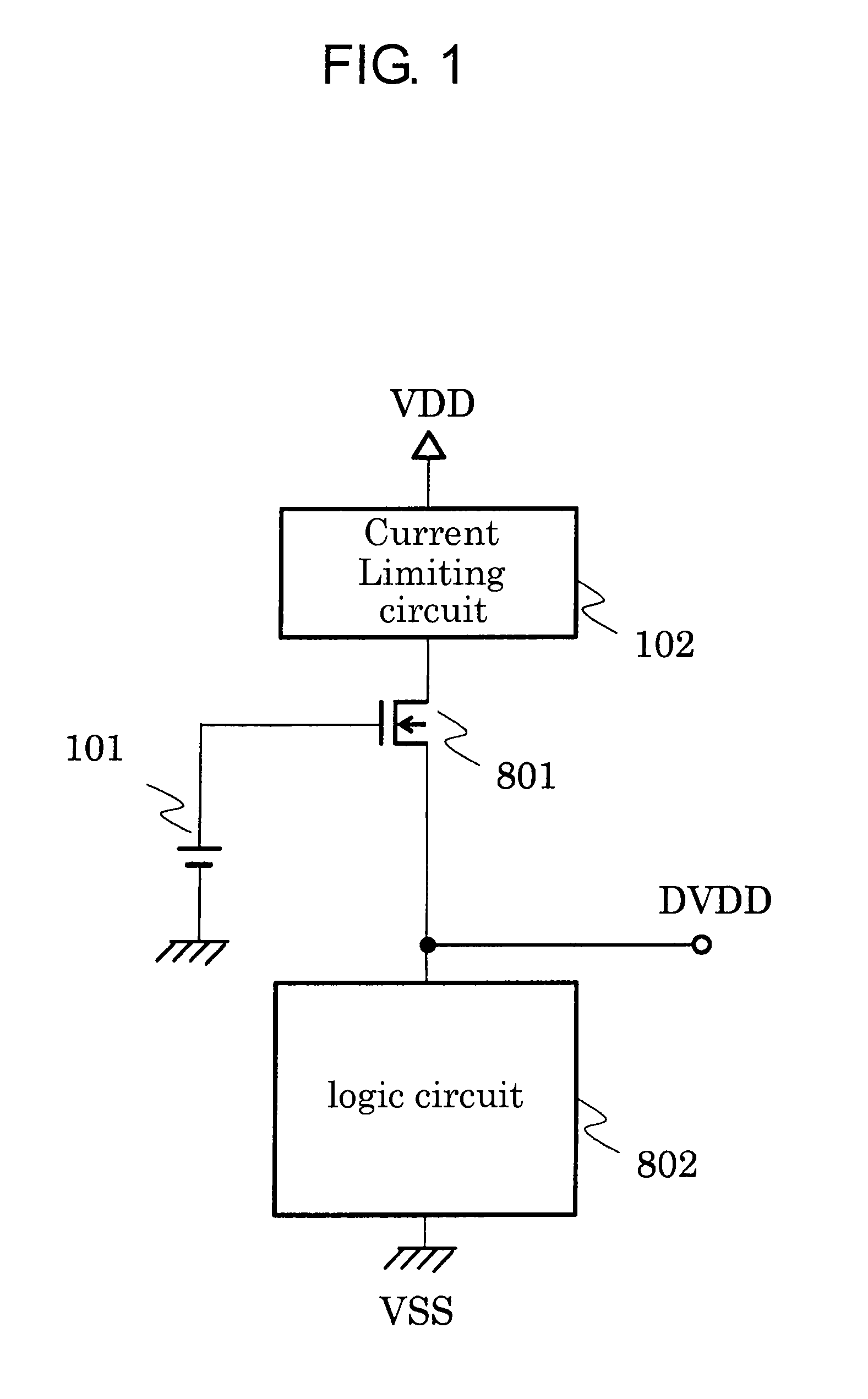
[0023]FIG. 1 is a block diagram illustrating an internal power supply voltage generation circuit according to an embodiment of the present invention. The difference between FIG. 1 and FIG. 7 resides in that a voltage source 101 for applying a gate voltage of the transistor 801 is provided and a current limiting circuit 102 is provided on the High side of the transistor 801.

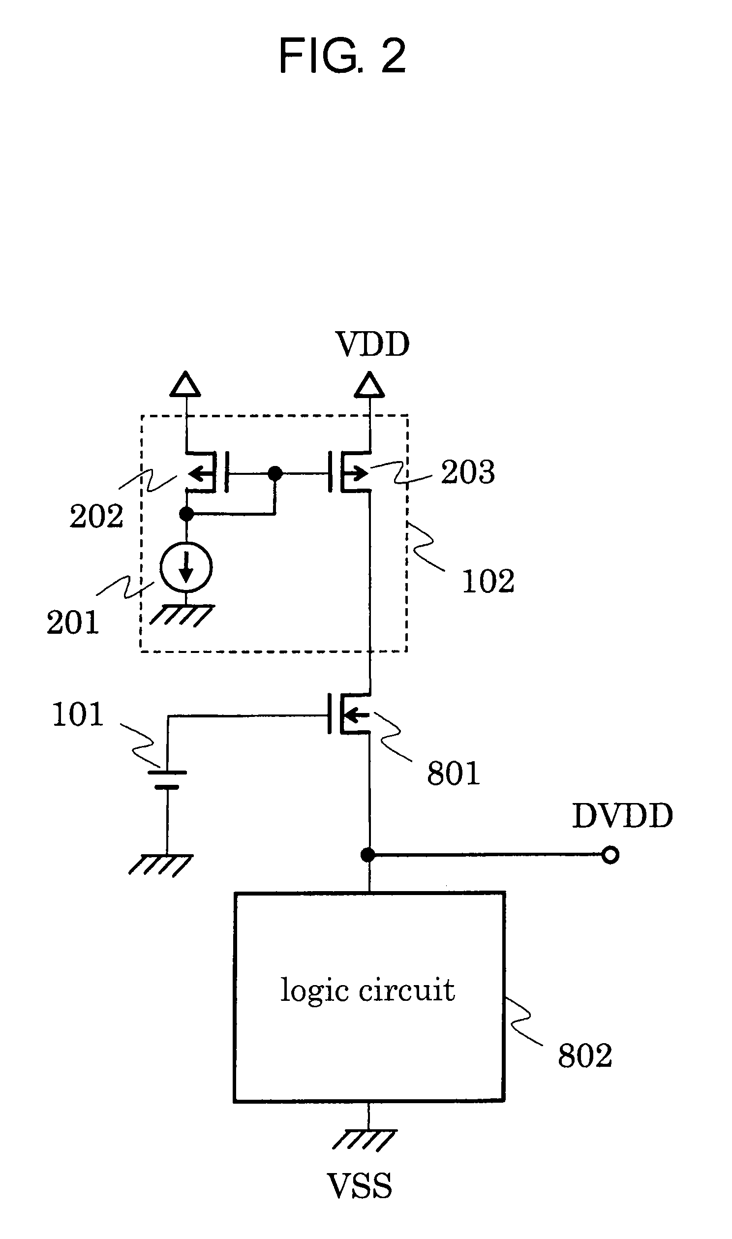
[0024]The current limiting circuit 102 has a function of limiting a maximum value of a current driven by the transistor 801. The current limiting circuit 102 is formed of, for example, a current mirror circuit as illustrated in FIG. 2, a depletion mode transistor as illustrated in FIG. 3, or a resistor as illustrated in FIG. 4.

[0025]Hereinafter, an operation of the internal power supply voltage generation circuit according to this embodiment is described.

[0026]When the logic circuit 802 operates, a through current flows therein. The voltage source 101 applies an appropriate voltage to a gate of the transistor 801 ...


PUM


Abstract

Provided is an internal power supply voltage generation circuit, with which a through current can be prevented from being excessive due to manufacturing fluctuations during the operation of a logic circuit, to thereby suppress current consumption. Provided is an internal power supply voltage generation circuit for generating an internal power supply voltage at an internal power supply terminal and supplying the internal power supply voltage to a logic circuit, the internal power supply voltage generation circuit including: a transistor having a source follower configuration for outputting a voltage applied to a gate thereof; and a current limiting circuit for limiting a maximum current of the transistor having the source follower configuration for outputting the voltage applied to the gate thereof, to thereby suppress a maximum current supplied to the logic circuit and suppress current consumption.

Description

RELATED APPLICATIONS[0001]This application claims priority under 35 U.S.C. §119 to Japanese Patent Application No. 2011-031295 filed on Feb. 16, 2011, the entire content of which is hereby incorporated by reference.BACKGROUND OF THE INVENTION[0002]1. Field of the Invention[0003]The present invention relates to an internal power supply voltage generation circuit for generating an internal power supply voltage at an internal power supply terminal and supplying the internal power supply voltage to a logic circuit.[0004]2. Description of the Related Art[0005]A conventional internal power supply voltage generation circuit is described. FIG. 7 is a circuit diagram illustrating the conventional internal power supply voltage generation circuit.[0006]A saturation-connected transistor 801 having a source follower configuration decreases a power supply voltage VDD applied to a gate thereof to an internal power supply voltage DVDD, and outputs the internal power supply voltage DVDD. With the in...

Claims


Application Information

Patent Timeline
Patent Type & Authority Applications(United States)
IPC IPC(8): G05F3/02
CPCG05F3/08G05F3/02G05F3/22G05F3/24G05F3/26
Inventor SUGIURA, MASAKAZU
Owner SEIKO INSTR INC
Why Eureka
Try Eureka