Synthetic Aperture Radar Image Formation System and Method

a radar and synthetic aperture technology, applied in the field of synthetic aperture radar, can solve the problems of data value saturation, method failure, and abundant problem in signal acquisition and processing system, and achieve the effect of increasing the quality of sar images and being efficient in implementation

Active Publication Date: 2012-08-16
MITSUBISHI ELECTRIC RES LAB INC
View PDF7 Cites 22 Cited by
  • Summary
  • Abstract
  • Description
  • Claims
  • Application Information

AI Technical Summary

Benefits of technology

[0020]According to embodiments of the invention, the formation of synthetic aperture radar (SAR) images is formulated as an inverse problem. The embodiments of the invention increase the quality of the SAR images when there is data saturation, specifically by optimizing a one-sided quadratic cost function to provide consistency with the received data. The SAR acquisition process is modeled using a linear function. The function is efficient to implement and can be used together with its adjoint in an iterative optimization process. The method controls azimuth ambiguities and incorporates image models to enable reconstruction from saturated SAR data.

Problems solved by technology

Such problems are abundant in signal acquisition and processing systems.
A common inverse problem in signal processing is the recovery of a signal x from a set of measurements y,
If the acquisition function A is invertible and the noise is negligible, an obvious choice is to use the inverse of the function A to determine x. However, that method can fail if A is not injective, i.e., the data can be explained by multiple signals, or if there is substantial noise.
Saturation of data values is a significant problem in SAR signal acquisition because of large fluctuations in data amplitudes and the use of low-precision quantizers.
Conventional image formation methods, such as the CSA, usually do not address data saturation specifically.
Signal saturation is a very common problem encountered in analog-to-digital (A / D) conversion systems because electronic components have a finite voltage range beyond which the signal amplitude is not allowed to vary.
Specifically, increasing the gain of the signal and promoting saturation also increases the signal-to-quantization noise ratio in the unsaturated measurements.

Method used


Image

  • Synthetic Aperture Radar Image Formation System and Method
  • Synthetic Aperture Radar Image Formation System and Method
  • Synthetic Aperture Radar Image Formation System and Method

Examples


Embodiment Construction

[0024]We represent a linear system with a finite dynamic range by

y=S(Ax),  (3)

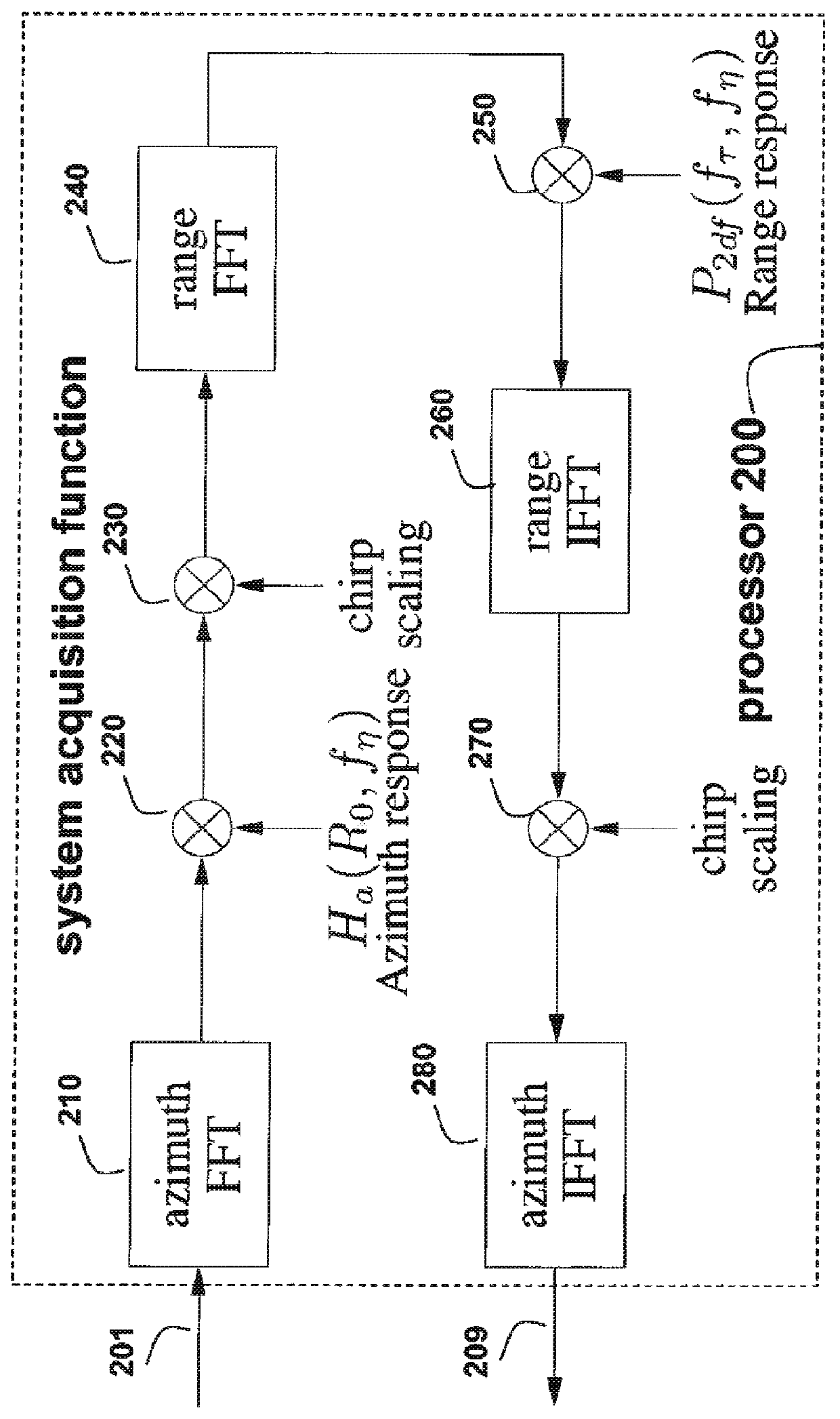
where A is a system acquisition function, and S(•) is a non-linear scalar saturation function

S(x)=sign(x)min{|x|,T}  (4)

applied element-wise to all the components of the input signal.

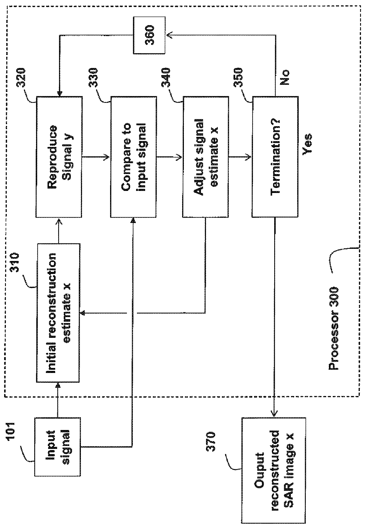
[0025]Instead of using a conventional least-squares fidelity criterion, we enforce a one-sided quadratic penalty on saturated measurements to ensure consistent image reconstruction. More specifically, for the quadratic penalty, we use a cost function

f(y,Ax)=12∑iri2(yi,(Ax)i),(5)ri(yi,(Ax)i)={(Ax)i-yiyiT((Ax)i-T)-yi≥+T((Ax)i+T)+yi≤-T,(6)

where (y)−=min(y, 0), (y)+=max(y, 0), and i indexes the real and imaginary parts of the data separately. As an advantage, the cost function penalizes inconsistent solutions, is simple to optimize, and, due to its quadratic nature, reduces additive noise before the saturation occurs.

[0026]Although minimizing the saturation-robust cost function in Eqn. (5) often produces acceptable solutions, a si...


PUM


Abstract

A saturated input signal acquired by a synthetic aperture radar (SAR) system is processed by estimating a reconstruction that generated the input signal, reproducing an input signal from an estimated reconstruction to generate a reproduced signal, comparing the reproduced signal with the input signal; adjusting an estimated reconstruction based on the comparison; and iterating from the reproducing step until a termination condition is reached.

Description

FIELD OF THE INVENTION[0001]This invention relates generally to synthetic aperture radar, and more particularly to forming high quality images from saturated data.BACKGROUND OF THE INVENTION[0002]Inverse Problems[0003]The study of inverse problems is a well-established discipline with several applications in a variety of fields, including signal processing and synthetic aperture radar (SAR) systems. The theory of inverse problems examines when and how a function can be inverted to infer the input from the output of the function. Such problems are abundant in signal acquisition and processing systems. The formulation of these problems as inverse problems has produced significant results in the areas of image de-noising, de-blurring and super-resolution.[0004]A common inverse problem in signal processing is the recovery of a signal x from a set of measurements y,y=A(x)+n,  (1)where the function A models the acquisition system, and n represents noise. The goal of the reconstruction pro...

Claims


Application Information

Patent Timeline
Patent Type & Authority Applications(United States)
IPC IPC(8): G01S13/90
CPCG01S13/9035G01S13/9011G01S13/904
Inventor BOUFOUNOS, PETROS T.WEI, DENNIS
Owner MITSUBISHI ELECTRIC RES LAB INC
Why Eureka
Try Eureka