Nanomechanical electric and electromagnetic field sensor

a technology of electric field and electromagnetic field, applied in the field of system for sensing electric field and/or electromagnetic field, can solve the problems of preventing the design and creation of compact electric field sensors, unable to exhibit high sensitivity over a broad frequency or wavelength range, and the size of the antenna-based system, so as to prevent the loss of charge

Inactive Publication Date: 2012-08-16
UT BATTELLE LLC
View PDF7 Cites 6 Cited by
  • Summary
  • Abstract
  • Description
  • Claims
  • Application Information

AI Technical Summary

Benefits of technology

[0007]The present invention is based on the interaction of an electric charge q with at least one of the electric field and the electromagnetic field. The electric charge is preferably localized on a cantilever and the cantilever is mounted generally perpendicular to a substrate. The substrate is preferably manufactured from a semiconductor material, for example silicon. In a preferred embodiment, the cantilever includes a stem and a tip which is positioned on the stem at a position opposite of the substrate. The tip is preferably manufactured from a material capable of maintaining the electric charge q and in a shape that allows for uniform distribution of the charge. In one embodiment, the tip is a glass microsphere. To localize the electric charge and to prevent the loss of charge, the stem is preferably made of an electrically nonconductive material.

Problems solved by technology

However, these antenna-based systems do not exhibit high sensitivity over a broad frequency or wavelength range.
Another drawback of these known systems is their size.
As a result, the dimensions of these known systems are relatively large, especially at lower frequencies, thereby preventing the design and creation of a compact electric field sensor.

Method used


Image

  • Nanomechanical electric and electromagnetic field sensor
  • Nanomechanical electric and electromagnetic field sensor
  • Nanomechanical electric and electromagnetic field sensor

Examples


Embodiment Construction

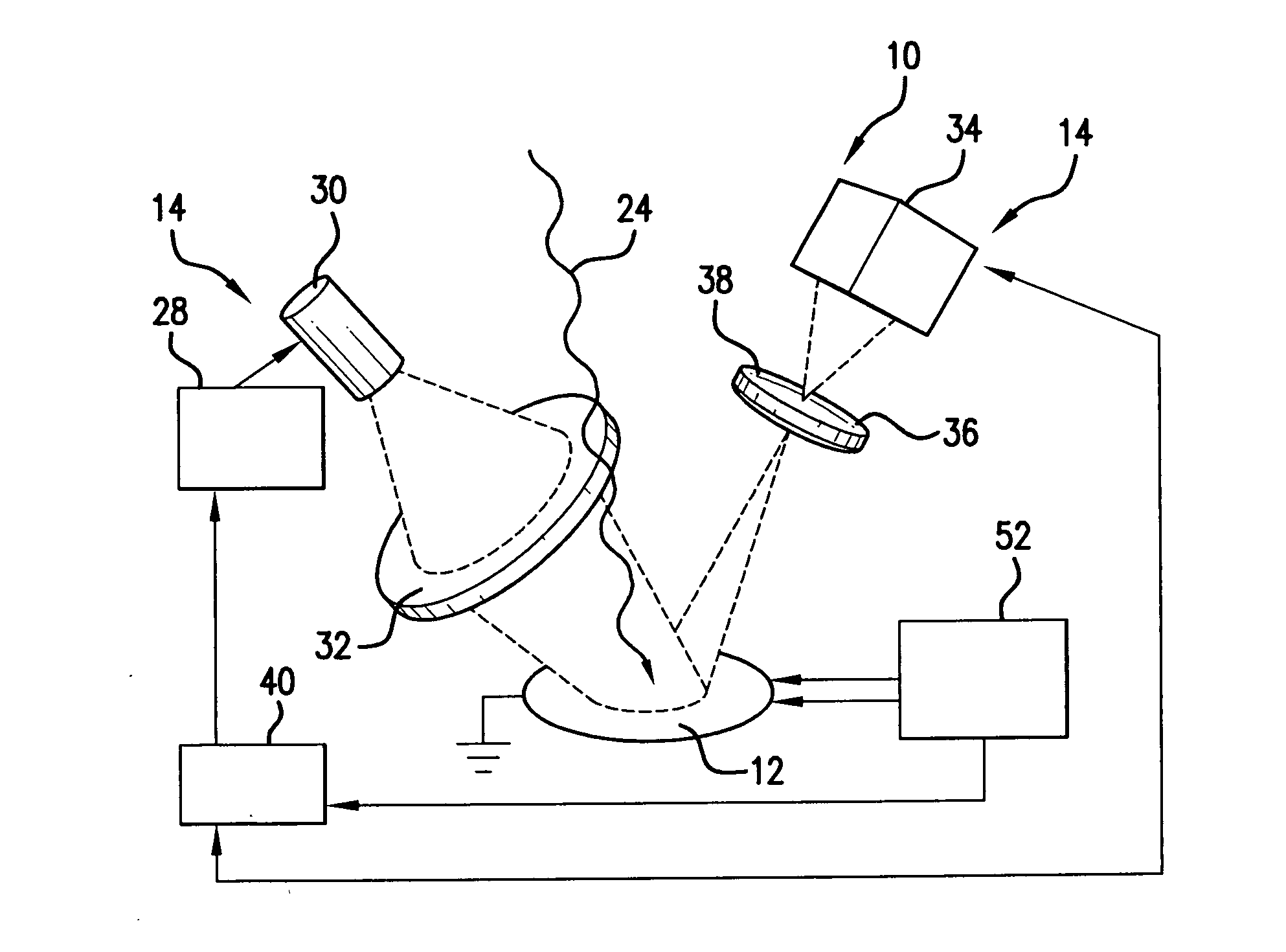
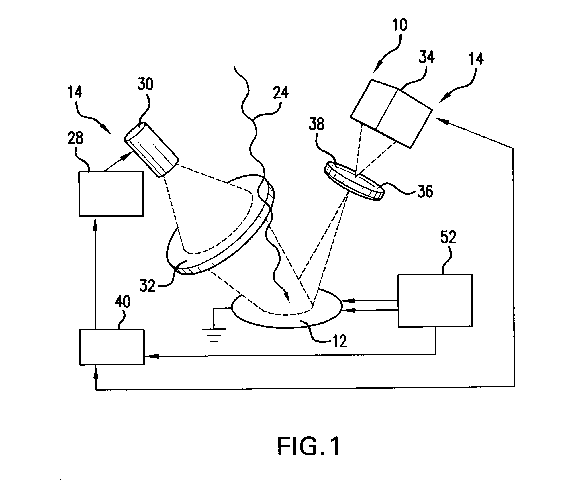
[0018]The present invention utilizes micro / nanomechanical structures (MNS) to detect an electric field and / or an electromagnetic field (a time varying electric field). The invention is based on the interaction of an electric charge, localized on a cantilever, with the electric field and / or the electromagnetic field. As used herein, to ease the description, references to the electric field are to be understood to refer to at least one of the electric field and the electromagnetic field.

[0019]FIG. 1 shows a preferred embodiment of a system 10 of this invention. In this embodiment, the system 10 includes a MNS 12 and a subsystem 14 for measuring and recording the movement of the MNS 12 in response to a target electric field. The system 10 is capable of detecting electric fields having a frequency from 10 (0.1) to 106 (109) Hz. In a preferred embodiment, the MNS 12 of this invention is disposed in an inert gas atmosphere.

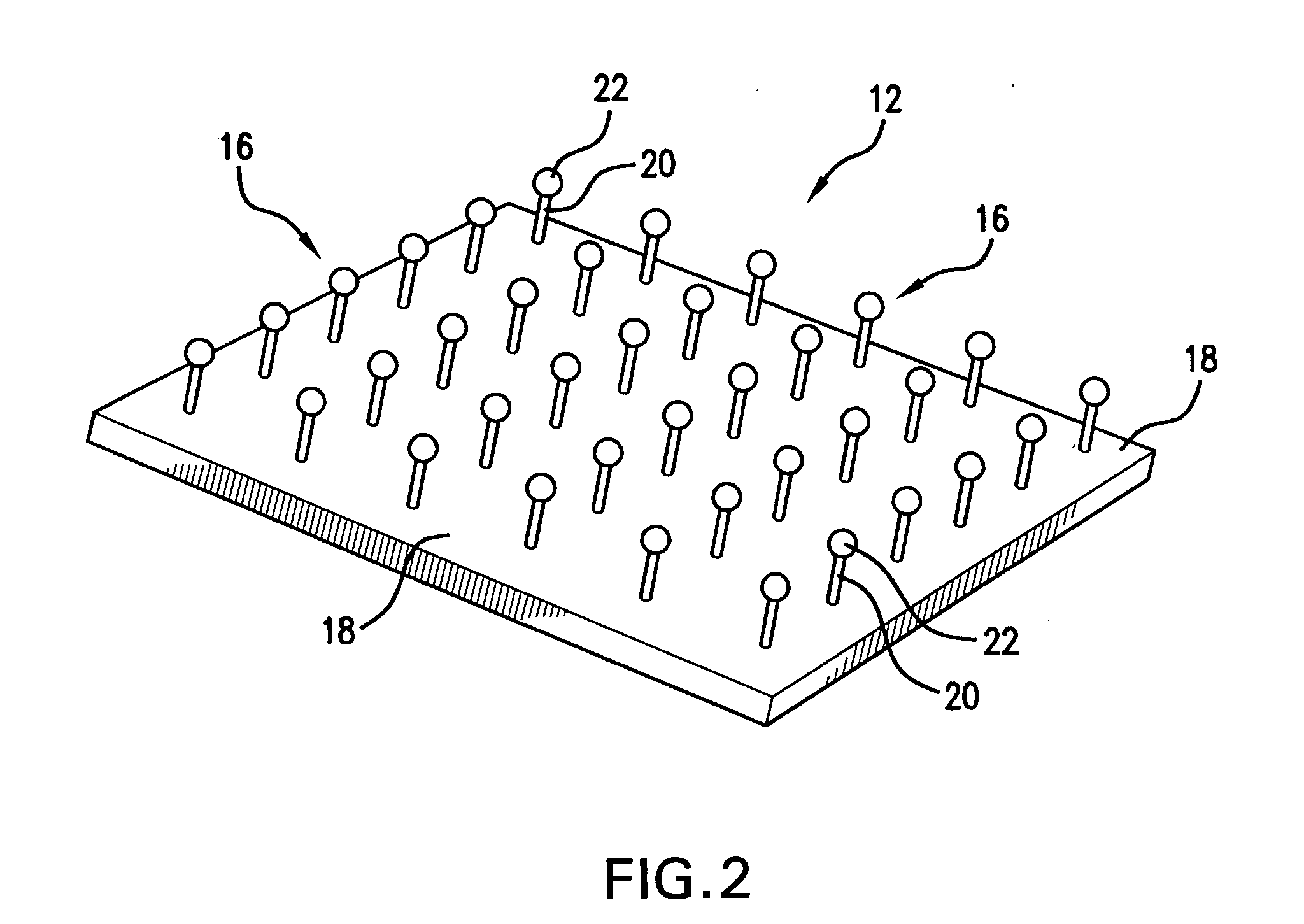
[0020]FIG. 2 shows the MNS 12, not necessarily shown to scale, acc...


PUM


Abstract

The present invention provides a system for detecting and analyzing at least one of an electric field and an electromagnetic field. The system includes a micro/nanomechanical oscillator which oscillates in the presence of at least one of the electric field and the electromagnetic field. The micro/nanomechanical oscillator includes a dense array of cantilevers mounted to a substrate. A charge localized on a tip of each cantilever interacts with and oscillates in the presence of the electric and/or electromagnetic field. The system further includes a subsystem for recording the movement of the cantilever to extract information from the electric and/or electromagnetic field. The system further includes a means of adjusting a stiffness of the cantilever to heterodyne tune an operating frequency of the system over a frequency range.

Description

GOVERNMENT RIGHTS[0001]This invention was made with government support under Contract No. DE-AC05-00OR22725 awarded by the U.S. Department of Energy. The government has certain rights in the invention.FIELD OF THE INVENTION[0002]The present invention relates to a system for sensing an electric field and / or an electromagnetic field. More particularly, the invention relates to a nanomechanical oscillator for sensing an electric field and / or an electromagnetic field, which is tunable over a frequency range.BACKGROUND OF THE INVENTION[0003]Known systems for sensing static electric fields and / or time-varying electric fields (electromagnetic fields) utilize an antenna and a receiver. In these known systems, the sensitivity of the system is dependent on the design of the antenna and the receiver electronics. However, these antenna-based systems do not exhibit high sensitivity over a broad frequency or wavelength range.[0004]Another drawback of these known systems is their size. The size of...

Claims


Application Information

Patent Timeline
Patent Type & Authority Applications(United States)
IPC IPC(8): H04N17/00G01R1/067
CPCG01R1/06738G01R29/0878G01R1/06744
Inventor DATSKOS, PANAGIOTIS GEORGELAVRIK, NICKOLAY
Owner UT BATTELLE LLC
Why Eureka
Try Eureka