Direct Illumination for Projection

Active Publication Date: 2012-08-16
PROJECTIONDESIGN
View PDF3 Cites 16 Cited by
  • Summary
  • Abstract
  • Description
  • Claims
  • Application Information

AI Technical Summary

Benefits of technology

[0007]Embodiments of the present invention are directed toward projection systems, devices, methods, and assemblies for improving the quality of projected images with an aspect ratio different from the aspect ratio of the imager device or micro-display used to produce the projected image. In such systems, the imager device can be operated with active and non-active areas. The active areas can include the pixels operated to produce a desired image, while the non-active pixels are operated in an “off” state to define a dark frame or boarder around the projected image. By matching the aspect ratio of the light integrator to the aspect ratio of the active area, which can be smaller than the total operable area of the imager device or micro-display, embodiments of the present invention can be configured to illuminate only the active area. By illuminating only the active area, embodiments of the present invention can reduce or eliminate the light that would otherwise be scattered or leaked from pixels in the non-active areas and projected onto the dark frame or boarders of the projected image. By reducing or eliminating the light projected onto the dark frame or boarders, the contrast ratio between the desired projected image and the dark frame or boarders can be improved, thus increasing the overall perceived quality of the projected image.

Problems solved by technology

Regardless of the type of imager chip, most projection systems are limited in their ability to produce a true black or dark pixel.
This limitation is based on each type of imager's inability to completely stop light from leaking through or scattering off pixels that are in the “off” state.
For example, the micromirrors on a DMD are not truly planar and even when an individual micromirror is angled to reflect the majority of light beyond a rejection angle of a total internal reflection (TIR) prism, some light is scattered onto an area of the viewing surface that is intended to be dark, thus reducing the ability of such projection systems to produce black or dark areas on the viewing surface.
This problem is exacerbated when the imager is operated with contiguous regions of pixels in the “off-state” because the amount of scattered light from such regions can cause black areas to appear gray or less than dark.
However, because of the limitations of the most imager chips to produce a truly dark region anywhere on the screen, the border or frame can appear to be gray and thus reduce the overall perceived contrast ratio of the projected image.
While the resulting Cinemascope image can be satisfactory for some applications, the visibility of the top and bottom bands due to leaked or scattered light from the non-active pixels can be distracting to viewers and reduce the perceived quality of the Cinemascope images.

Method used


Image

  • Direct Illumination for Projection
  • Direct Illumination for Projection
  • Direct Illumination for Projection

Examples


Embodiment Construction

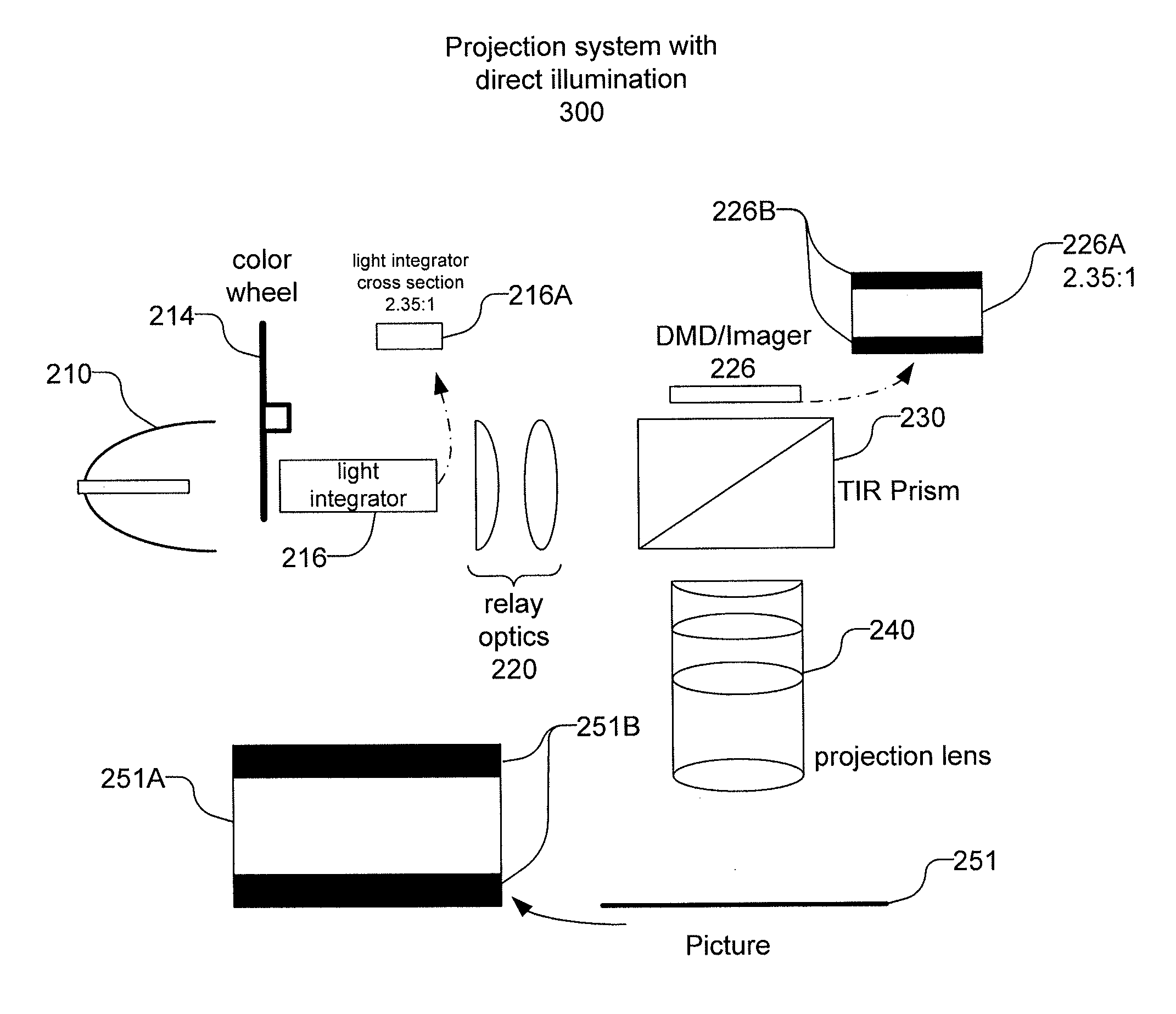
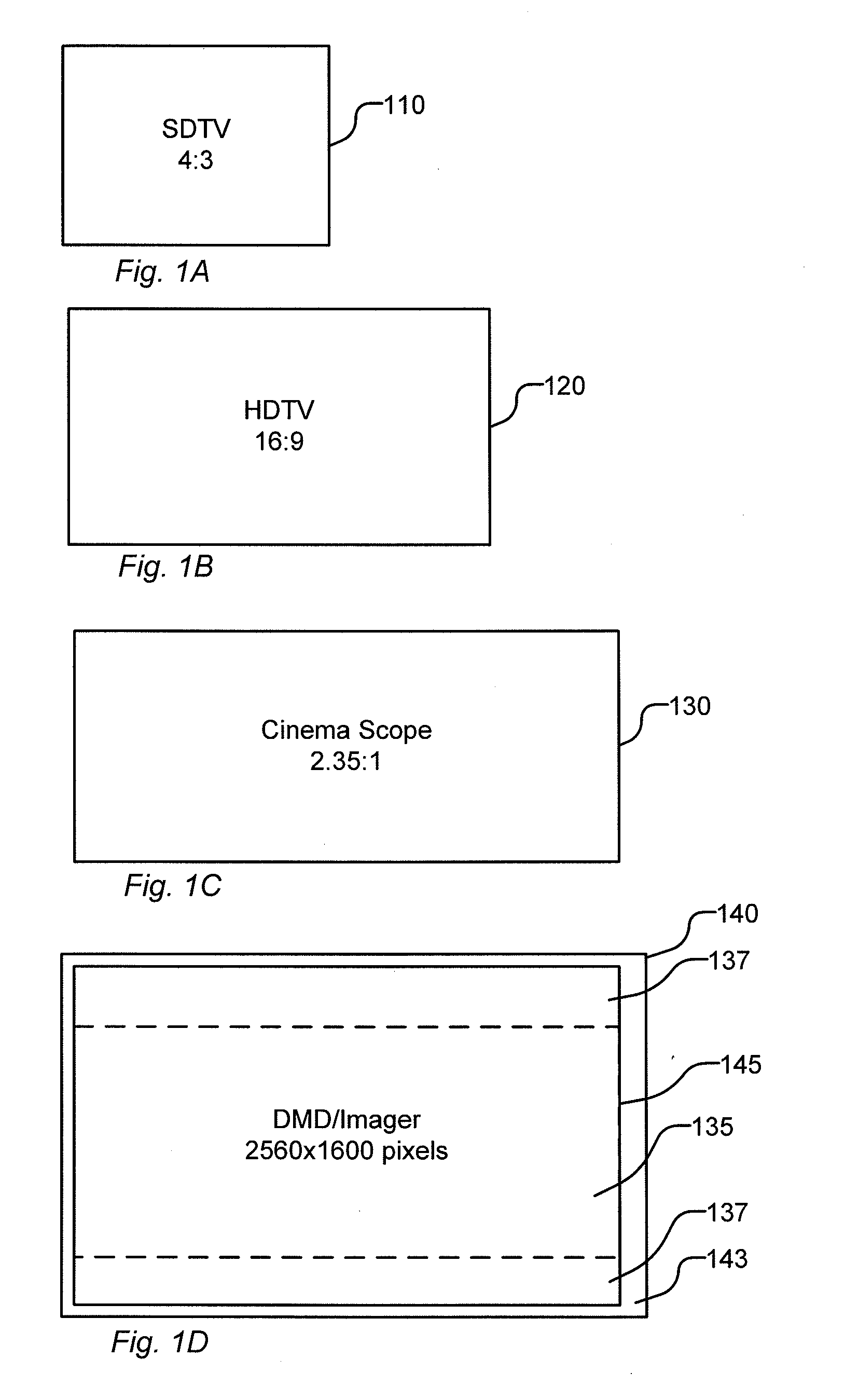
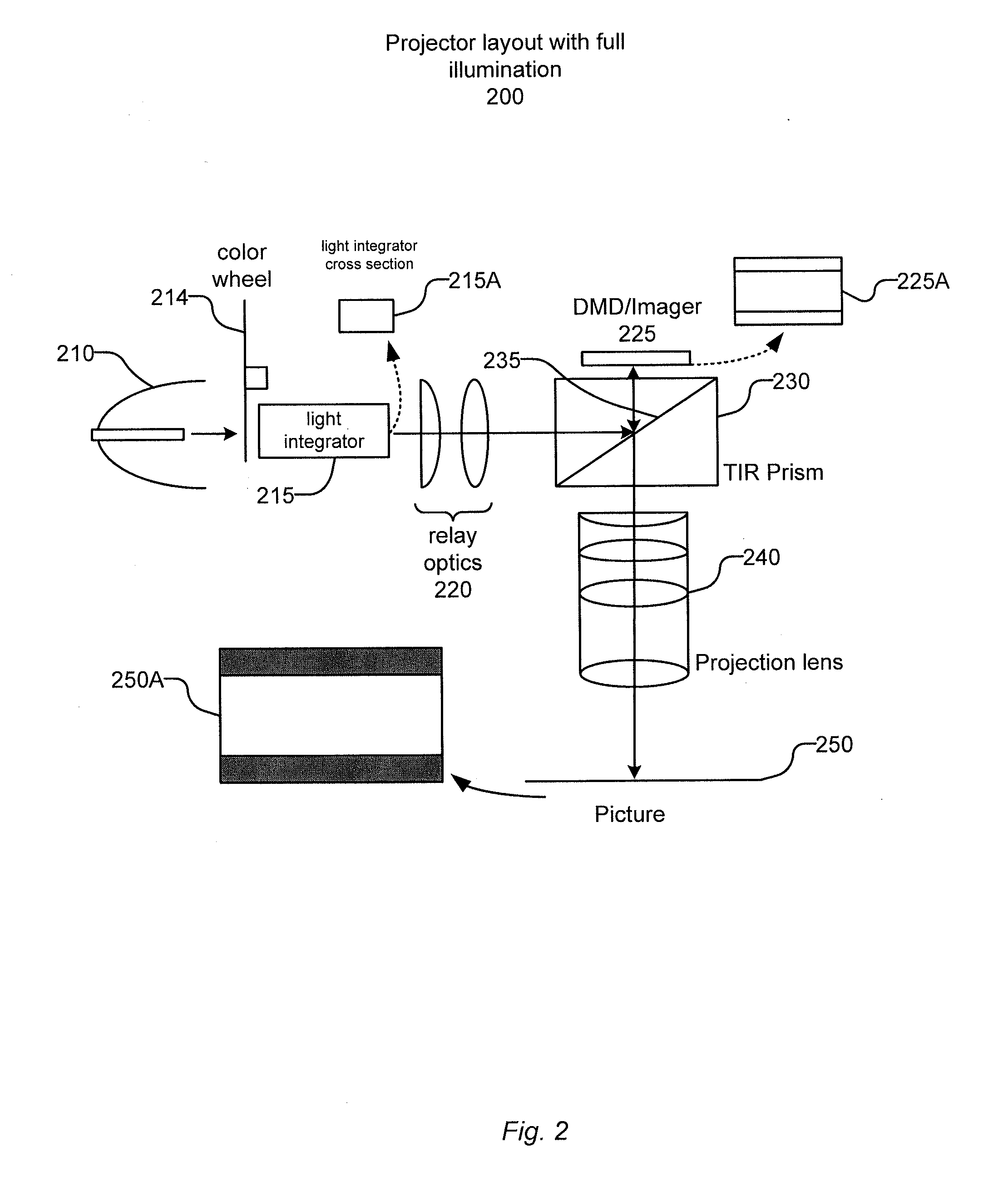
[0022]Embodiments of the present invention are directed towards projection optics, projection systems, and image and video projectors. Specifically, embodiments of the present invention are directed at improving the contrast ratio between the dark bands that frame or border a projected image or video that result from using and imager device with an active area that has an aspect ratio different from the aspect ratio of a desired projected image or video. To reduce or eliminate light scattered or leaked from non-active areas of an imager device, embodiments of the present invention are directed toward illuminating only the active area of the imager device that has the same aspect ratio as the desired projected image or video. According to various environments of the present invention, limiting which area of an imager device, such as a DMD, LCD or LCOS imager chips, can be achieved by shaping the aspect ratio of uniform illumination by using a light integrator with an output having th...


PUM


Abstract

Projection systems and apparatuses for providing high contrast projected images with an aspect ratio different from the aspect ratio of the imager or micro-display used are provided. Light integrators having an aspect ratio equal to the aspect ratio to the desired projected image or video can be inserted into the optical train of the projection system or apparatus to illuminate only an active area equal to having an aspect ratio equal to the aspect ratio of the desired projected image or be. By reducing the illuminated area of the imager, light scattered or otherwise diverted from pixels held in the “off state” in the non-active area of imager can be greatly reduced to provide darker dark levels in the frame surrounding the project image or video.

Description

BACKGROUND[0001]Embodiments of the present invention are generally directed towards video projection systems. Within the field of video projection, many systems using various imager technologies exist for projecting an image onto a viewing surface. By modulating the individual pixels on imager or micro-display device, light incident on the device can be manipulated to form high quality projected images. The form of light modulation varies based on the type of imager chip or micro-display used in the projection system. For example, imager chips can include transmissive, reflective and polarization switching pixels.[0002]Transmissive systems, such as those based on liquid crystal device (LCD) type light valves, selectively transmit pixels by blocking light incident on one side of the imager based on the image data sent to the imager. Similarly, reflective systems, such as those based on digital micromirror device (DMD) and reflective LCD type imagers, selectively reflect light inciden...

Claims


Application Information

Patent Timeline
IPC IPC(8): G03B21/14
CPCG03B21/208
Inventor OLSEN, KJELL EINARSIMONSEN, TOBBYLEFSAKER, SVERREERIKSEN, JØRN
Owner PROJECTIONDESIGN
Why Eureka
Try Eureka