Mechanism for Absorbing Kinetic Energy from Frontal Impacts of Vehicles Against Vehicle Restraining Systems, for Using on the Edges and Central Reservations of Roadways, Such as Shock Absorbers and Barrier Ends

Active Publication Date: 2012-08-16
HIERROS & APLANACIONES SA
View PDF9 Cites 8 Cited by
  • Summary
  • Abstract
  • Description
  • Claims
  • Application Information

AI Technical Summary

Benefits of technology

[0034]FIG. 6, with its sub-FIGS. 6a and 6b, shows a very efficient configuration of the ram (1) when the deformable profile (2) has an open cross-section in the form of a “U”, “C”, “sigma” or “omega”. The ram (1) comprises of a base plate (10) by way of support for a core (8) with the forward part (in the direction of advance) having the form of a wedge and with two wings (9) in their upper and lower ends, which do not cover the entire length of the ram (1), with two openings (12) remaining in the rear part thereof. The height of the core or ridge of the deformable profile (2) with open cross-section is greater than the height of the wedge-shaped front part of the core (8) of the ram (1) but less than the distance between the wings (9) of the ram and less, in turn, than the height of the rear part of said core (8) in such a way that, as the system has the ram (1) with its base (10) facing the ridge of the deformable profile (2) and, to the degree that the ram (1) is longitudinally displaced along the deformable profile (2), the wedge-shaped attack surfaces (11) of the core (8) of the ram (1) force the wings of the deformable profile (2) to open and spread out, being plastically deformed and with both wings of the profile (2) projecting through the openings (12) of the rear part of the ram (1).

Problems solved by technology

In those locations where vehicles need to be protected from a frontal impact against the obstacle or element of risk on the roadside and such protection cannot be guaranteed with longitudinal barriers, another kind of device is installed known as “impact attenuators” or sometimes also “impact dampers”.

Method used


Image

  • Mechanism for Absorbing Kinetic Energy from Frontal Impacts of Vehicles Against Vehicle Restraining Systems, for Using on the Edges and Central Reservations of Roadways, Such as Shock Absorbers and Barrier Ends
  • Mechanism for Absorbing Kinetic Energy from Frontal Impacts of Vehicles Against Vehicle Restraining Systems, for Using on the Edges and Central Reservations of Roadways, Such as Shock Absorbers and Barrier Ends
  • Mechanism for Absorbing Kinetic Energy from Frontal Impacts of Vehicles Against Vehicle Restraining Systems, for Using on the Edges and Central Reservations of Roadways, Such as Shock Absorbers and Barrier Ends

Examples


Embodiment Construction

[0014]The present invention provides a new mechanism for the absorption of kinetic energy from the frontal impact of a vehicle against a containment system which, incorporating a containment system for vehicles such as an impact attenuator or a barrier terminal, has advantages with respect to the present state of the art in that it optimizes the features of the system in terms of:

[0015]1. Better controlled performance and efficiency of energy absorption along the length of the system.

[0016]2. Total stability of functioning over time.

[0017]3. Greater durability.

[0018]4. Lower economic cost.

[0019]5. Greater ease of repair and better reutilization.

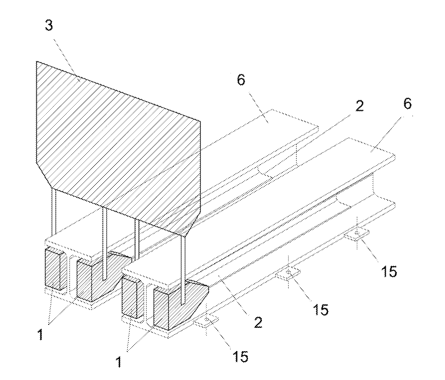
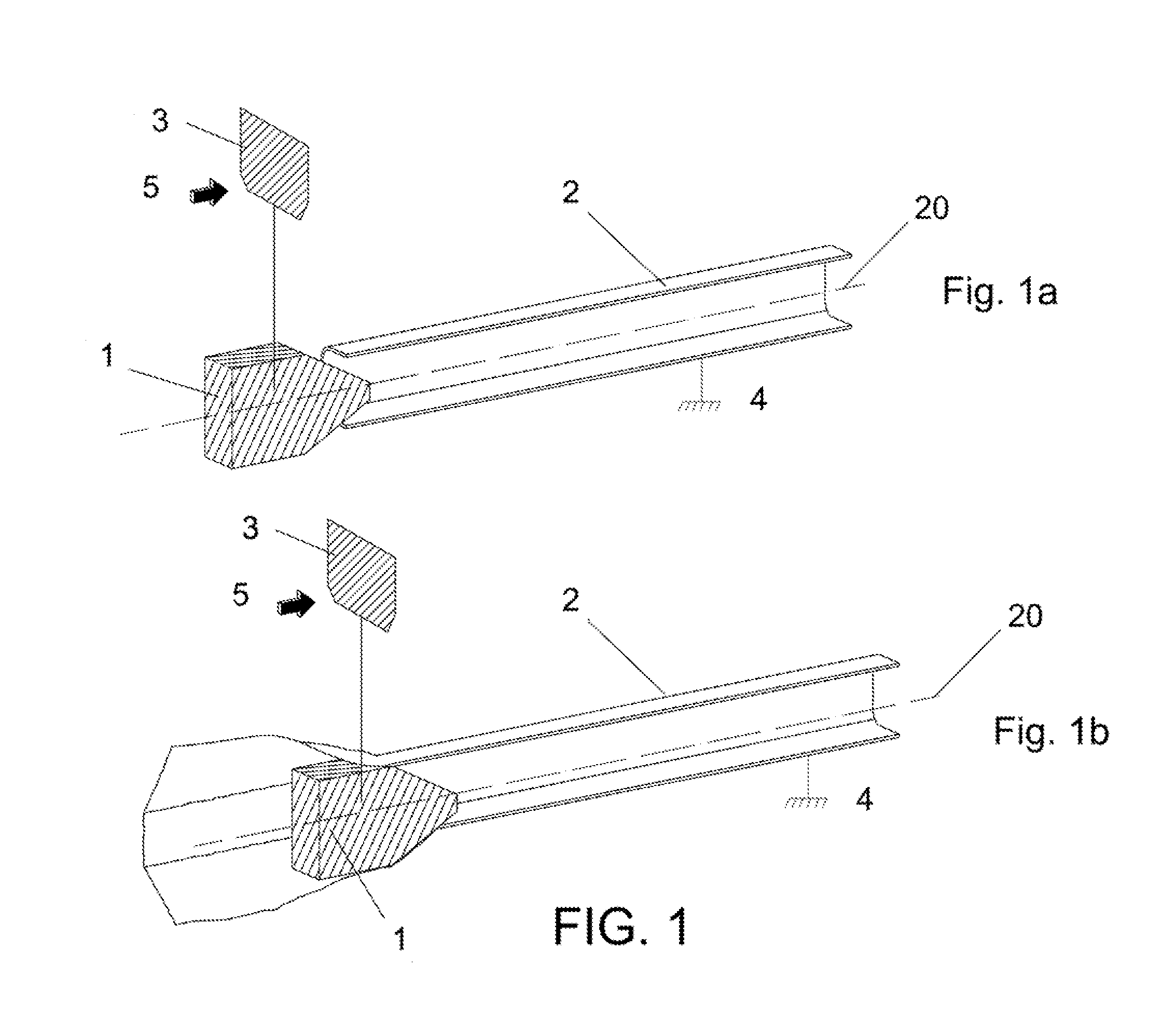
[0020]This new mechanism for the absorption of kinetic energy from the frontal impact of a vehicle against a containment system such as an impact attenuator or barrier terminal basically comprises two interrelated elements as shown in FIG. 1, sub-FIG. 1a.

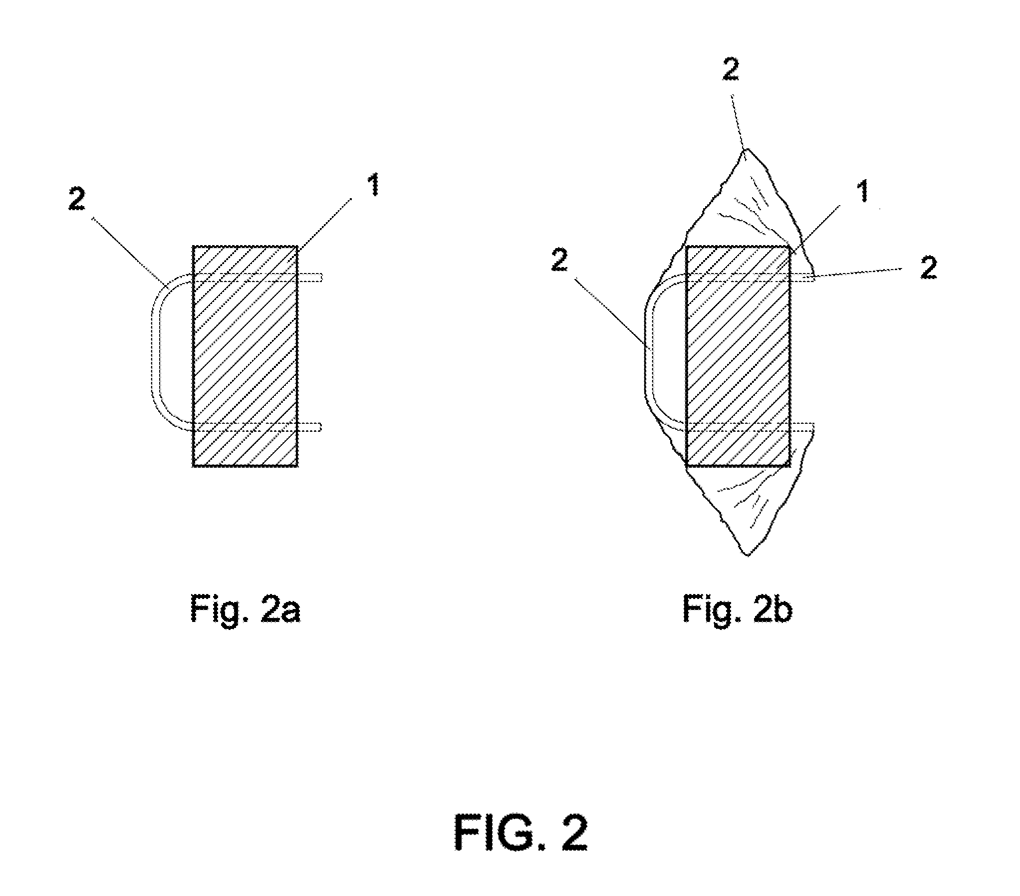
[0021]Rigid body by way of an impact element or ram (1)

[0022]Deformable metallic profile...


PUM


Abstract

A mechanism for the absorption of the kinetic energy of a vehicle frontally impacting against a containment system, such as an impact attenuator or barrier terminal, by means of the longitudinal propagation of the plastic deformation of one or more longitudinal deformable metallic profiles produced by means of a rigid ram which is displaced along the deformable profile, intercepting part of its cross-section, joined to a structural element of the system which receives and transmits the impact of the vehicle being displaced along the containment system, the deformable profile being directly or indirectly fixed to the ground and therefore remaining static during the impact.

Description

OBJECT OF THE INVENTION[0001]The present invention relates to a mechanism for the absorption of the kinetic energy of the frontal impact of a vehicle against a vehicle containment system for use on the sides and central reservations of roads, such as an impact attenuator or a safety barrier terminal, basically comprising of a rigid body by way of an impact element or “ram” and a deformable longitudinal profile, the “ram” being attached directly or indirectly to the structural element of the containment system which receives and transmits the frontal impact of a vehicle to the system and is in turn capable of being displaced longitudinally along it, said “ram” being arranged in the system in such a way that, when it is longitudinally displaced together with the structural element due to the latter receiving the stresses coming from the frontal impact of a vehicle, its cross-section partially or wholly intercepts the cross-section of the deformable metallic profile which is directly o...

Claims


Application Information

Patent Timeline
Patent Type & Authority Applications(United States)
IPC IPC(8): E01F15/00
CPCE01F15/143E01F15/146E01F15/00F16F7/12
Inventor AMENGUAL PERICAS, ANTONIO
Owner HIERROS & APLANACIONES SA
Why Eureka
Try Eureka