
Method of manufacturing a multiple of identical gears by means of cutting machining

Active Publication Date: 2012-08-16
LIEBHERR VERZAHNTECHNIK GMBH
View PDF123 Cites 14 Cited by
  • Summary
  • Abstract
  • Description
  • Claims
  • Application Information

AI Technical Summary

Benefits of technology

[0005]It is therefore the object of the present invention to provide a method of manufacturing gears which allows an even higher accuracy in the manufacture of gears.
[0032]The data transfer can in this respect advantageously take place electronically. This allows a particularly simple data transfer.

Problems solved by technology

Due to tolerances becoming tighter and tighter and to the ever higher demands on gear cutting accuracy, the previously used corrections are not or are no longer sufficient to meet the high demands on the cut gear geometry.
Defects in the tool, axial alignment errors, concentricity errors, wobbles, geometric errors and errors from irregular tool heating result in deviations which can make difficult or prevent a passing of statistical process evaluations with the demanded tolerances.

Method used


Image

  • Method of manufacturing a multiple of identical gears by means of cutting machining
  • Method of manufacturing a multiple of identical gears by means of cutting machining
  • Method of manufacturing a multiple of identical gears by means of cutting machining

Examples


first embodiment

[0050]the present invention will now be presented with reference to FIG. 4, wherein deviations in the cut gear geometry in shifting which are caused by pitch deviations in the tool can be compensated. In this respect, pitch deviations in the tool can result in fluctuations of the tooth thickness along the tool which also present as tooth thickness change (or spherical dimension change) or tooth width change in the workpieces. The compensation of this tooth thickness variation takes place in accordance with the invention via a corresponding engagement of the X axis in dependence on the shift position.

[0051]For this purpose, the magnitude of the tooth thickness change must first be determined for the total shift range with reference to the spherical dimension or the tooth width. For this purpose, the spherical dimension or the tooth width is determined at individual sampling points over the shift range and a corresponding interpolation is carried out. On a linear interpolation, the di...

second embodiment

[0055]the method in accordance with the invention will now be presented with reference to FIG. 5. In this respect, a parameter of the workpieces specific to the cut gear is measured and statistically detected over the production process. In this respect, the deviation from the spherical dimension is entered in FIG. 5 in μm for the workpieces A1 to A29. As can be seen from the drawing, in this respect a saw tooth design is given which repeats with every shift run in the multi-cycle shifting used. The same effect is, however, also present in the conventional fine shifting, with the deviations, however, being distributed over a larger number of workpieces, that is the saw tooth is considerably wider or presents itself in the form of a ramp.

[0056]In accordance with the invention, the measurement data on the already machined workpieces can now be evaluated and can enter into the control of the NC axes in the following machining cycle. In this respect, in particular a change in the X spac...


PUM


Abstract

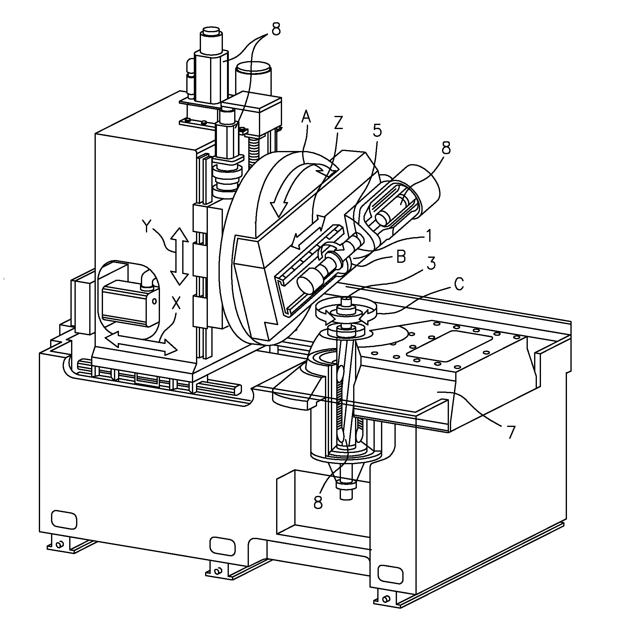
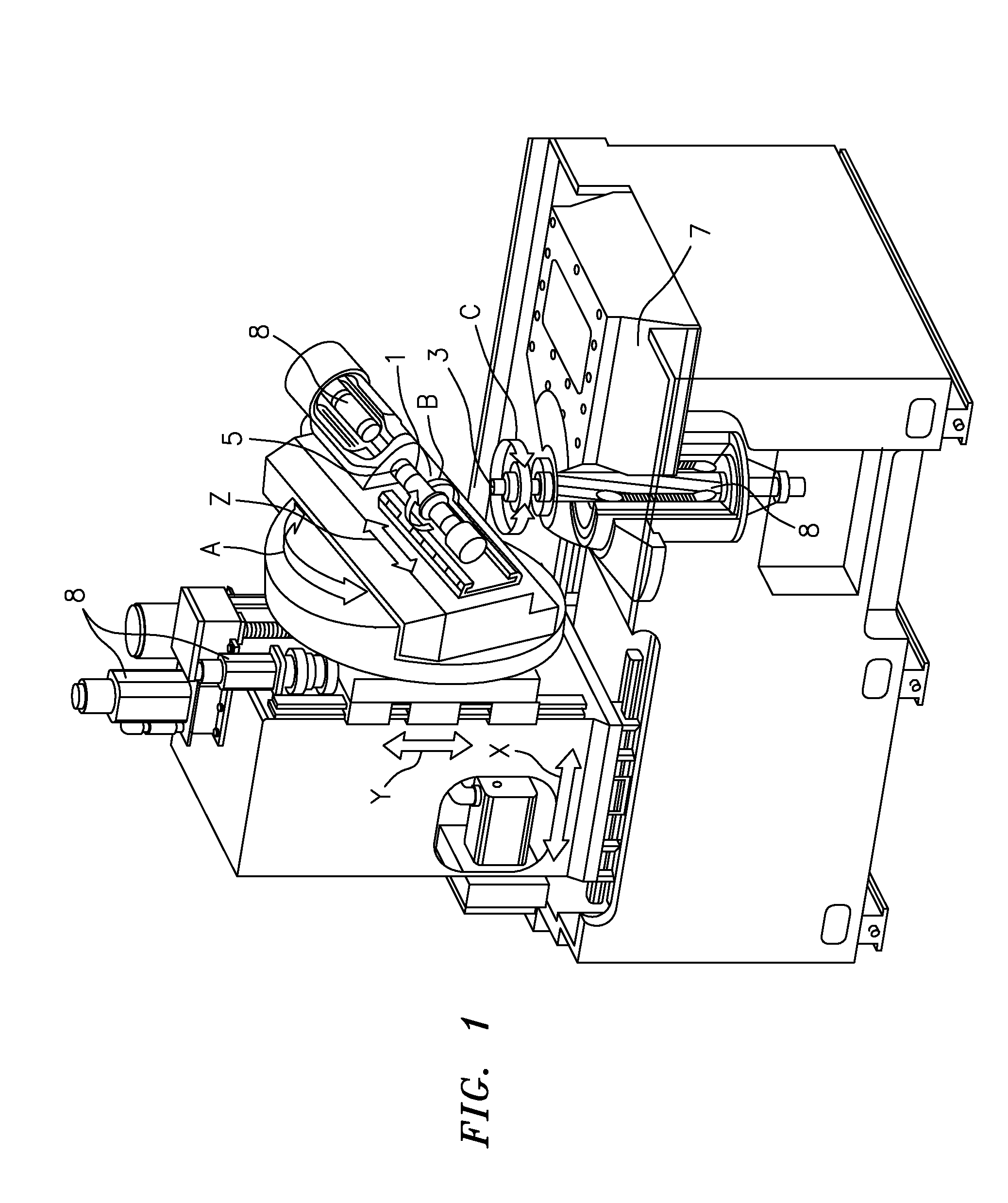
The invention relates to method of manufacturing a multiple of identical gears by means of cutting machining, in particular hob cutting or hob grinding, on a gear-cutting machine, wherein workpieces are machined by means of a rotating tool which is brought into engagement with the workpiece via the control of NC axes of the gear cutting machine. In accordance with the invention, deviations from workpiece to workpiece are compensated by a respective different control of at least one of the NC axes of the gear cutting machine.

Description

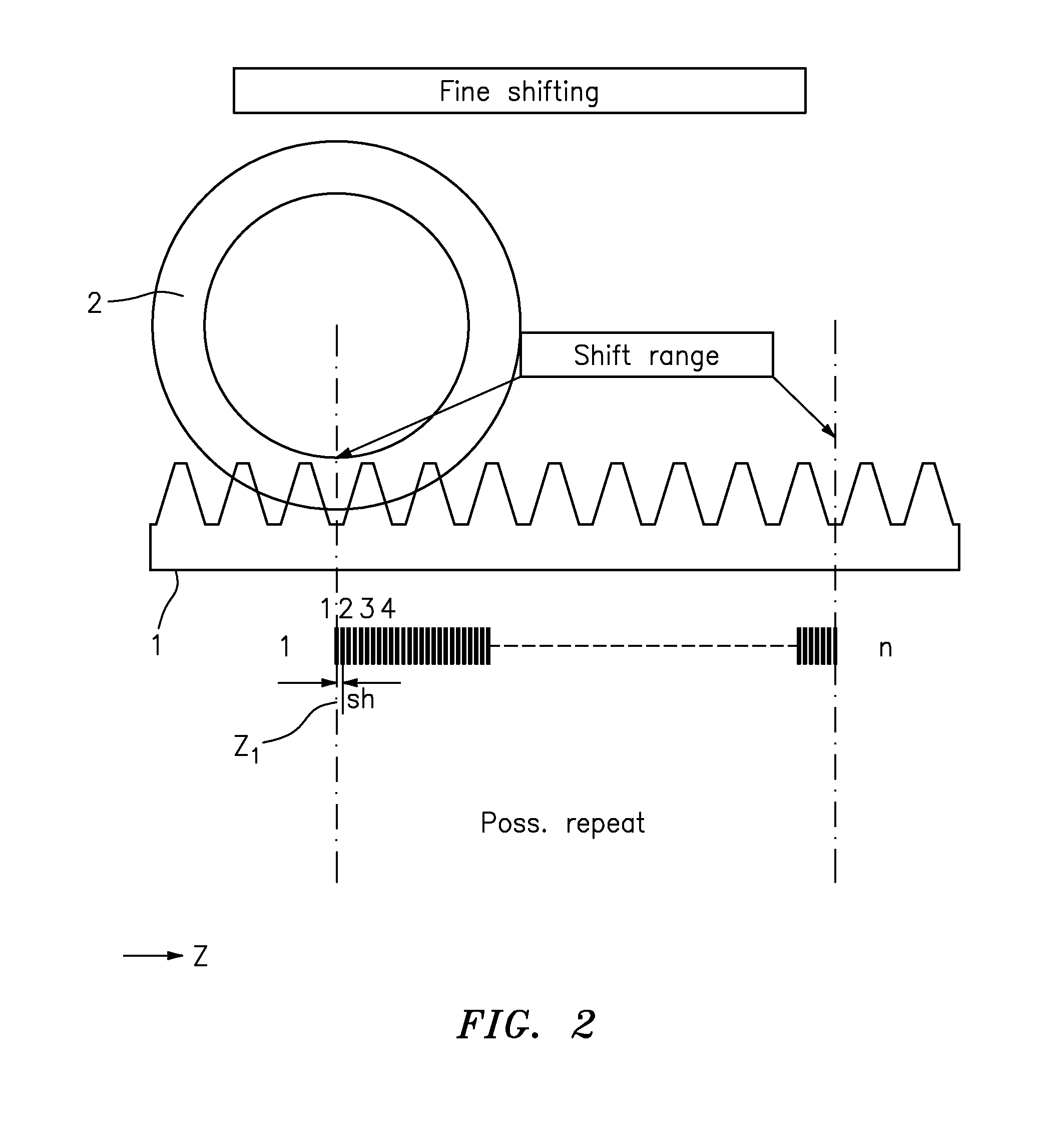
BACKGROUND OF THE INVENTION[0001]The present invention relates to a method of manufacturing a plurality of identical gears by means of cutting machining on a gear cutting machine. It is in this respect in particular a method of manufacturing gears by means of hob cutting or hob grinding. The gear cutting machine is accordingly a hob cutting machine and / or a hob grinding machine.[0002]In the method in accordance with the invention, workpieces are machined by means of a rotating tool, in particular by means of a hob cutter or by means of a worm grinding wheel, wherein the tool is brought into engagement with the workpiece via the control of NC axes of the gear cutting machine. The rotary movements of the tool and of the workpiece are in particular mutually coupled in this respect.[0003]In this respect, the tool can be shifted by a certain distance along its axis of rotation in the course of the machining of a plurality of workpieces, and in particular on a change between workpieces, t...

Claims


Application Information

Patent Timeline
IPC IPC(8): G05B19/00
CPCB23F23/1218F16H1/16G05B19/19
Inventor WINKEL, OLIVERBODENMULLER, ERWIN
Owner LIEBHERR VERZAHNTECHNIK GMBH
Learn More