
Method for operating a turbocharger arrangement and control unit for a turbocharger arrangement

a technology of control unit and turbocharger, which is applied in the direction of electric control, combustion engines, exhaust treatment, etc., can solve the problems of low-pressure turbine bypass valve failure, and achieve the effects of less weight, less power, and small siz

Active Publication Date: 2012-08-23
FORD GLOBAL TECH LLC
View PDF12 Cites 25 Cited by
  • Summary
  • Abstract
  • Description
  • Claims
  • Application Information

AI Technical Summary

Benefits of technology

[0010]In this way, engine operating parameters may be used to determine a position of the low-pressure turbine bypass valve. If it is determined that the low-pressure turbine bypass valve has degraded, for example if the valve is stuck in a fully open or fully closed position, control of engine boost pressure may be adapted to compensate for the degraded valve. Further, the position of the valve may be determined without using a position sensor, lowering costs and reducing control strategy complexities and resources.

Problems solved by technology

However, due to a variety of reasons, the low-pressure turbine bypass valve may fail, being stuck in the fully closed or in the fully open position, for example.

Method used


Image

  • Method for operating a turbocharger arrangement and control unit for a turbocharger arrangement
  • Method for operating a turbocharger arrangement and control unit for a turbocharger arrangement
  • Method for operating a turbocharger arrangement and control unit for a turbocharger arrangement

Examples


Embodiment Construction

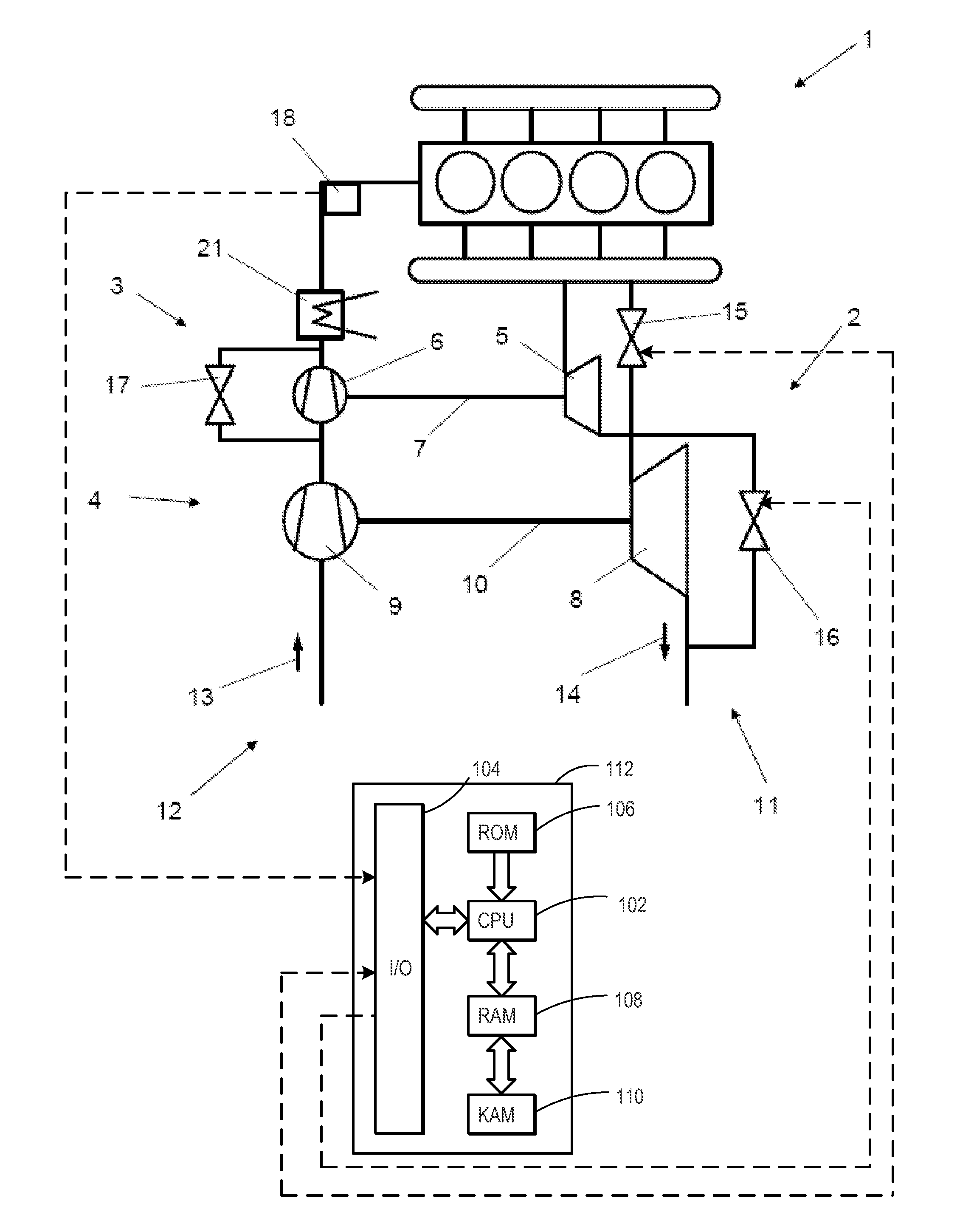
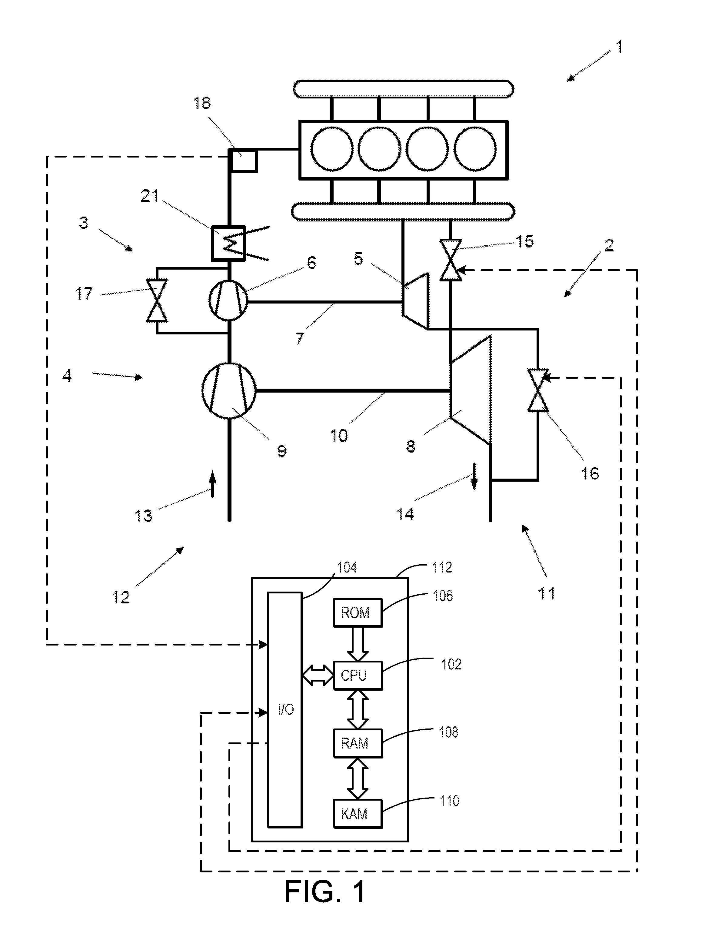
[0019]A turbocharger arrangement of an internal combustion engine refers to a turbocharger arrangement or turbocharger system comprising a low-pressure turbocharging stage and a high-pressure turbocharging stage, which are arranged sequentially. The low-pressure turbocharging stage comprises a low-pressure turbocharger, which, in particular, comprises a low-pressure turbine driving a low-pressure compressor. The high-pressure turbocharging stage comprises a high-pressure turbocharger, comprising a high-pressure turbine driving a high-pressure compressor. The high-pressure compressor is arranged downstream the low-pressure compressor in the intake airflow of the internal combustion engine. The low-pressure turbine is located downstream the high-pressure turbine in the exhaust flow of the engine.

[0020]The low-pressure turbine exhibits a low-pressure turbine bypass valve (wastegate), which is not equipped with a position sensor providing a feedback signal representative of the actual p...


PUM


Abstract

A method for operating a turbocharger arrangement of an internal combustion engine, the turbocharger arrangement comprising a low-pressure and a high-pressure turbocharging stage arranged sequentially, the low-pressure turbo-charging stage comprising a low-pressure turbine with a sensorless low-pressure turbine bypass valve, is provided. The method comprises evaluating at least one sensor signal of the turbocharger arrangement for detecting a failure mode of the sensorless low-pressure turbine bypass valve. In this way, the low-pressure turbine bypass valve may be monitored for degradation without utilizing a position sensor.

Description

RELATED APPLICATIONS[0001]The present application claims priority to European Patent Application No. 11155167.7, filed on Feb. 21, 2011, the entire contents of which are hereby incorporated by reference for all purposes.FIELD[0002]The present disclosure relates to a method for operating a turbocharger arrangement of an internal combustion engine and a control unit for such a turbocharger arrangement.BACKGROUND AND SUMMARY[0003]Internal combustion engines, in particular diesel and gasoline engines, are frequently equipped with turbochargers. A turbocharger operates by compression of the intake airflow into the engine in order to achieve more power. In particular, a predetermined power can be generated by a turbocharged engine with a smaller displacement volume and thus smaller size and less weight, thereby achieving an increased specific power and a reduction of fuel consumption.[0004]In general, turbochargers are driven by the exhaust flow of the internal combustion engine. To this ...

Claims


Application Information

Patent Timeline
IPC IPC(8): F02D23/00
CPCF02B39/16F02B37/002F02B2039/166F02B2039/168F02D41/0007F02D41/1445F02D41/1448F02D41/18F02D41/221F02D2200/0406Y02T10/40F01N2900/1406F01N2900/1411F02B37/013F02B37/183Y02T10/144F02B2039/164Y02T10/12
Inventor CHEVALIER, ALAIN MARIE ROGERPETROVIC, SIMONBARTSCH, ARNO
Owner FORD GLOBAL TECH LLC
Learn More