Corona igniter with improved corona control

a technology of corona and igniter, which is applied in the field of corona igniter, can solve the problems of significant energy loss at the firing end of the igniter, low relative permittivity of air, and difficult arc formation, and achieve the effects of preventing ionization in the gaps, robust ignition, and preventing energy from flowing through the gaps

Inactive Publication Date: 2012-08-23
FEDERAL MOGUL IGNITION
View PDF28 Cites 32 Cited by
  • Summary
  • Abstract
  • Description
  • Claims
  • Application Information

AI Technical Summary

Benefits of technology

[0012]The filler material keeps air and gas from the surrounding manufacturing environment and the combustion chamber out of the gaps, and thus prevents the formation of ionized gas between the central electrode and the insulator or between the insulator and the shell, both of which can form a conductive path, corona discharge, or arcing between the central electrode and the cylinder head. The filler material prevents ionization in the gaps and prevents energy from flowing through the gaps. Thus, the corona igniter provides a more concentrated corona discharge at the central electrode firing end and a more robust ignition, compared to corona igniters of the prior art.

Problems solved by technology

Corona discharge ignition systems provide an alternating voltage and current, reversing high and low potential electrodes in rapid succession which makes arc formation difficult and enhances the formation of corona discharge.
The significant drop is due to the low relative permittivity of air.
FIG. 14 illustrates that the high voltage drop across the air gaps leads to a spike in electric field strength at the gaps, which tends to ionize the air in the gaps leading to significant energy loss at the firing end of the igniter.
In addition, the ionized air in the gaps is prone to migrating toward the central electrode firing end, forming a conductive path across the insulator to the shell or the cylinder head, and reducing the effectiveness of the corona discharge at the central electrode firing end.
The conductive path across the insulator may lead to arcing between those components, which is oftentimes undesired and reduces the quality of ignition at the central electrode firing end.

Method used


Image

  • Corona igniter with improved corona control
  • Corona igniter with improved corona control
  • Corona igniter with improved corona control

Examples


Embodiment Construction

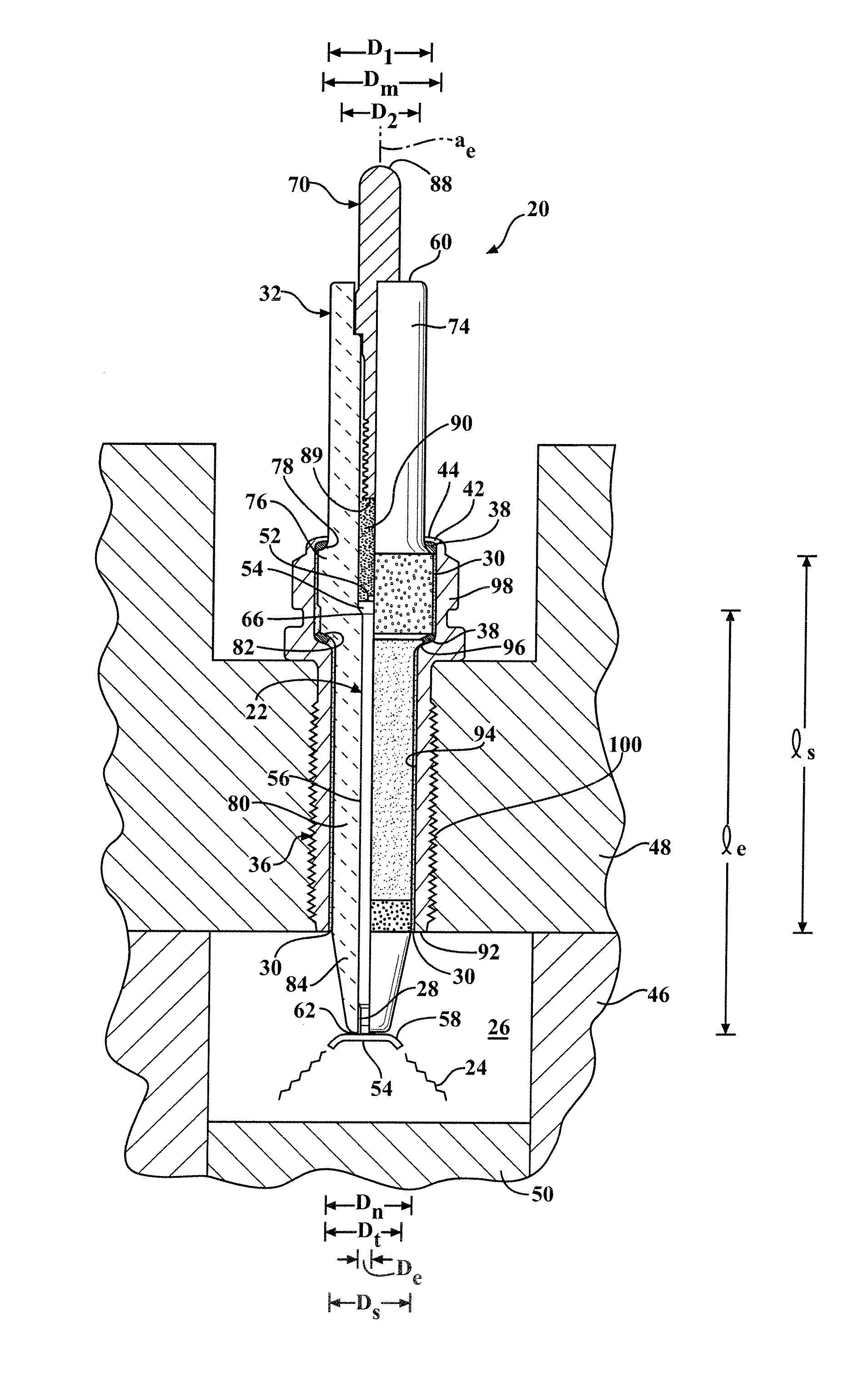
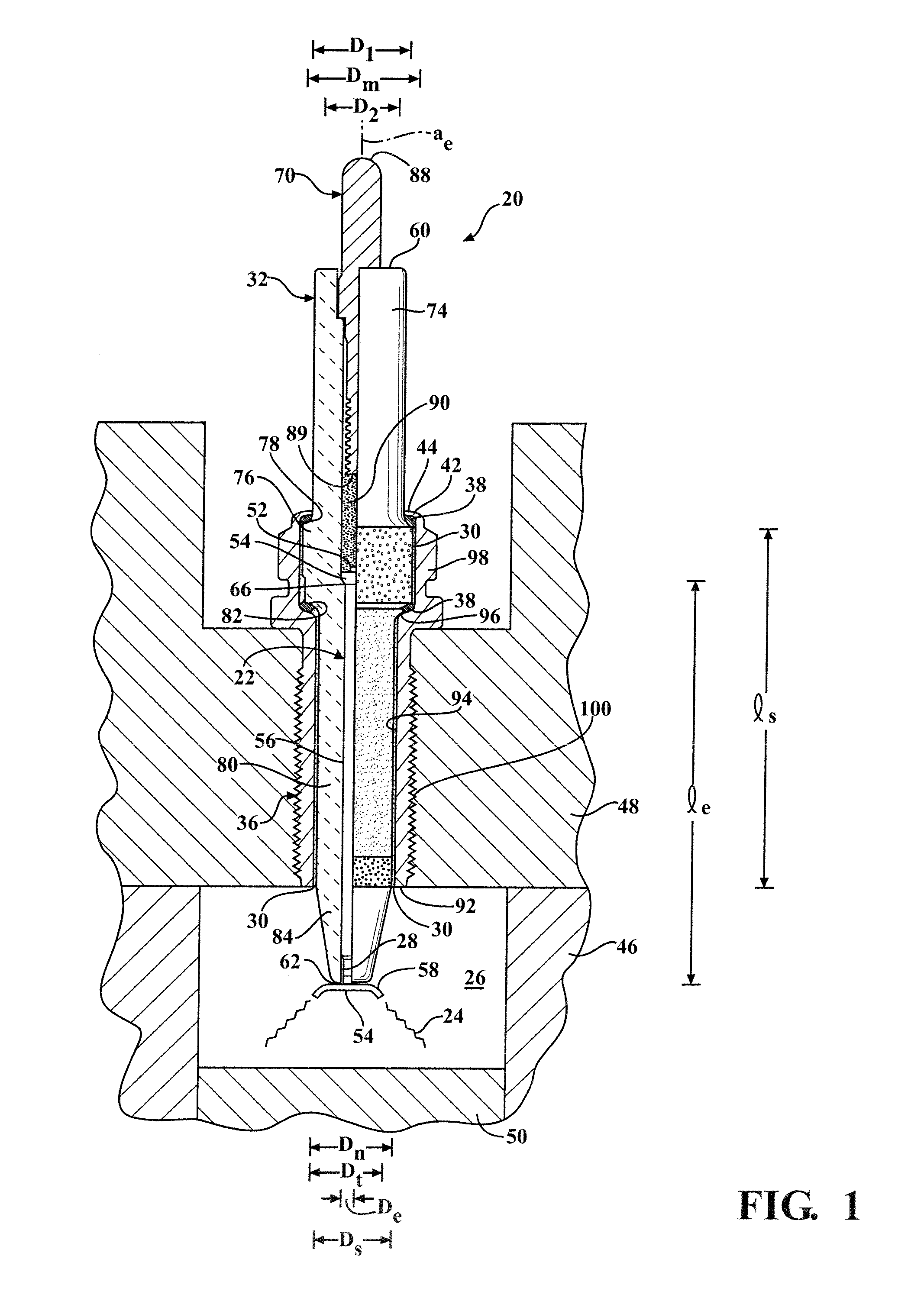
[0028]One aspect of the invention provides a corona igniter 20 for a corona discharge ignition system, as shown in FIG. 1. The system intentionally creates an electrical source which suppresses the formation of an arc and promotes the creation of strong electrical fields which produce corona. The ignition event of the corona discharge ignition system includes multiple electrical discharges running at approximately 1 megahertz.

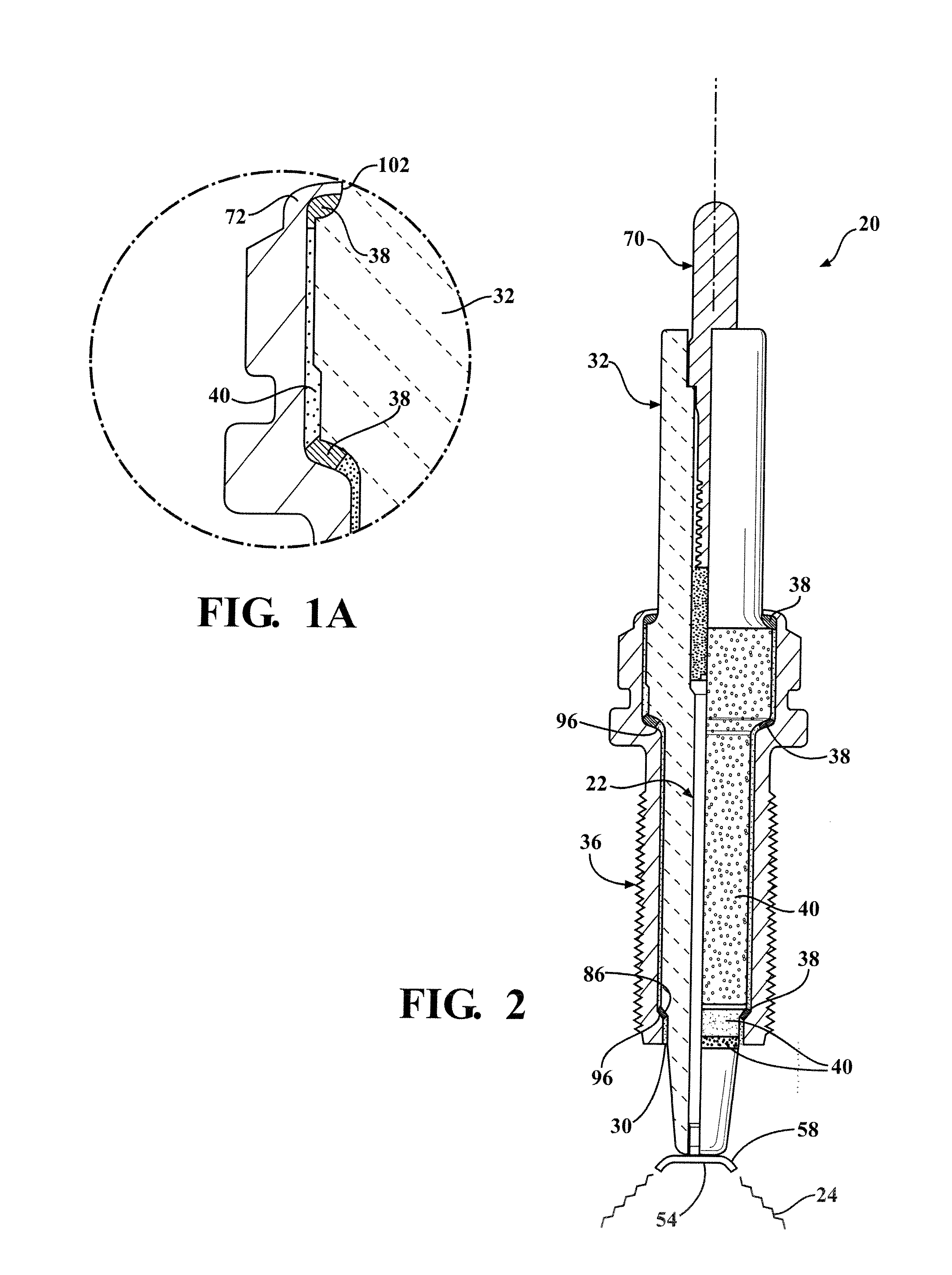
[0029]The igniter 20 of the system includes a central electrode 22 for receiving energy at a high radio frequency voltage and emitting a radio frequency electric field to ionize a portion of a combustible fuel-air mixture and provide a corona discharge 24 in a combustion chamber 26 of an internal combustion engine. The corona igniter 20 is assembled such that the clearance between the central electrode 22, insulator 32, and shell 36 results in small air gaps. The assembly method first includes inserting the central electrode 22 into the insulator 32 such that a...


PUM

PropertyMeasurementUnit
frequencyaaaaaaaaaa
relative permittivityaaaaaaaaaa
shell gap widthaaaaaaaaaa

Abstract

A corona igniter 20 includes an electrode gap 28 between the central electrode 22 and the insulator 32 and a shell gap 30 between the insulator 32 and the shell 36. The gaps 28, 30 are filled with a filler material 40 to prevent corona discharge 24 in the gaps 28, 30 and to concentrate the energy at a firing tip 58 of the central electrode 22. The filler material 40 may be electrically insulating or conductive. The shell gap width ws may be greatest at a shell lower end 92. The shell gap 30 may also be in a turnover region between a shell upper end 44 and the insulator 32, in which case the filler material 40 is injection molded around the turnover region. During operation of the igniter 20, the filler material 40 provides a reduced voltage drop across the gap 28, 30.

Description

CROSS REFERENCE TO RELATED APPLICATION[0001]This application claims the benefit of U.S. provisional application Ser. No. 61 / 422,838, filed Dec. 14, 2010.BACKGROUND OF THE INVENTION[0002]1. Field of the Invention[0003]This invention relates generally to a corona igniter for emitting a radio frequency electric field to ionize a fuel-air mixture and provide a corona discharge, and a method of forming the corona igniter.[0004]2. Related Art[0005]Corona discharge ignition systems provide an alternating voltage and current, reversing high and low potential electrodes in rapid succession which makes arc formation difficult and enhances the formation of corona discharge. The system includes a corona igniter with a central electrode charged to a high radio frequency voltage potential and creating a strong radio frequency electric field in a combustion chamber. The electric field causes a portion of a mixture of fuel and air in the combustion chamber to ionize and begin dielectric breakdown, ...

Claims


Application Information

Patent Timeline
Patent Type & Authority Applications(United States)
IPC IPC(8): F02P23/00H01F7/06H01T19/00
CPCH01T13/50Y10T29/4902H01T21/02H01T19/00
Inventor BURROWS, JOHN ANTONYLYKOWSKI, JAMES D.HAMPTON, KEITH
Owner FEDERAL MOGUL IGNITION
Why Eureka
Try Eureka