Trajectory modification of a spinning projectile

a technology of projectiles and trajectory modifications, applied in direction controllers, instruments, weapons, etc., can solve the problems of large amount of power, failure to provide a trajectory modification method that utilizes drag devices or drag devices in conjunction with spin control methods, etc., and achieve the effect of reducing power consumption, cost and complexity

Active Publication Date: 2012-08-23
GEN DYNAMICS ORDNANCE & TACTICAL SYST
View PDF23 Cites 14 Cited by
  • Summary
  • Abstract
  • Description
  • Claims
  • Application Information

AI Technical Summary

Benefits of technology

[0025]The inventions described herein also provide for an absence of control actuators on a drag device thereby reducing power consumption, cost and complexity.

Problems solved by technology

The use of a Magnetically Actuated Friction (MA) brake or a Magneto-Rheological (MR) fluid brake in conjunction with an external aerosurface as described in U.S. Pat. No. 7,412,930 “Frictional Roll Control Apparatus for a Spinning Projectile,” describes a low weight and low power consumption method for de-spinning and orienting the guidance section of a projectile, but fails to provide a trajectory modification method that utilizes a drag device or that utilizes a drag device in conjunction with a spin controlling method.
However, the electro-mechanical device alone would need to be large to overcome the rotational inertia of the spinning guidance section thereby requiring large amounts of power for de-spinning and orienting the guidance section of a projectile.

Method used


Image

  • Trajectory modification of a spinning projectile
  • Trajectory modification of a spinning projectile
  • Trajectory modification of a spinning projectile

Examples


Embodiment Construction

[0036]The invention disclosed herein could be applied to many different types of projectiles including but not limited to the 60 mm, 81 mm and 120 mm mortar rounds, artillery rounds such as the 105 mm and 155 mm round and the 2.75″ Hydra Rocket. The invention incorporates a Roll Control Device (RCD). The invention may incorporate an electronic navigation system, such as a Global Positioning System (GPS) or Inertial Navigation System (INS) or a combination of navigation systems.

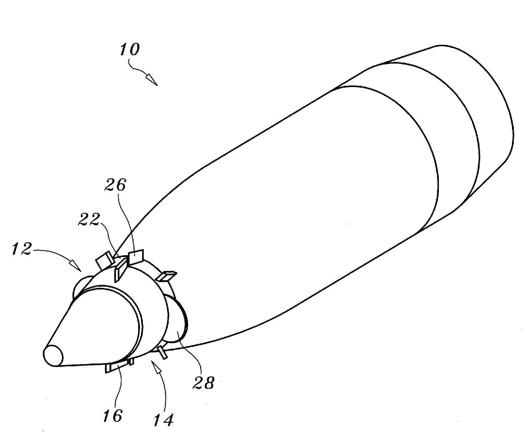
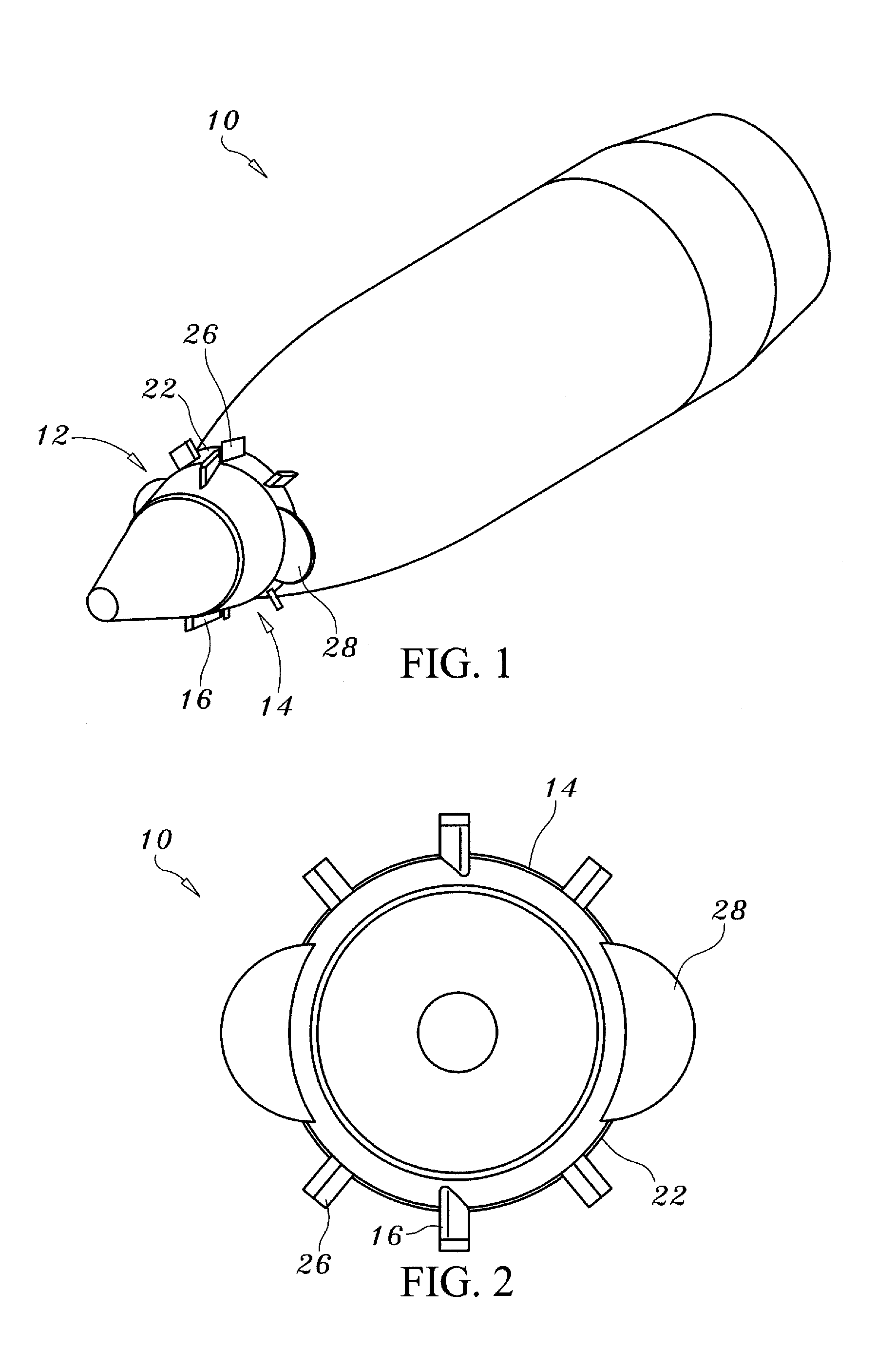
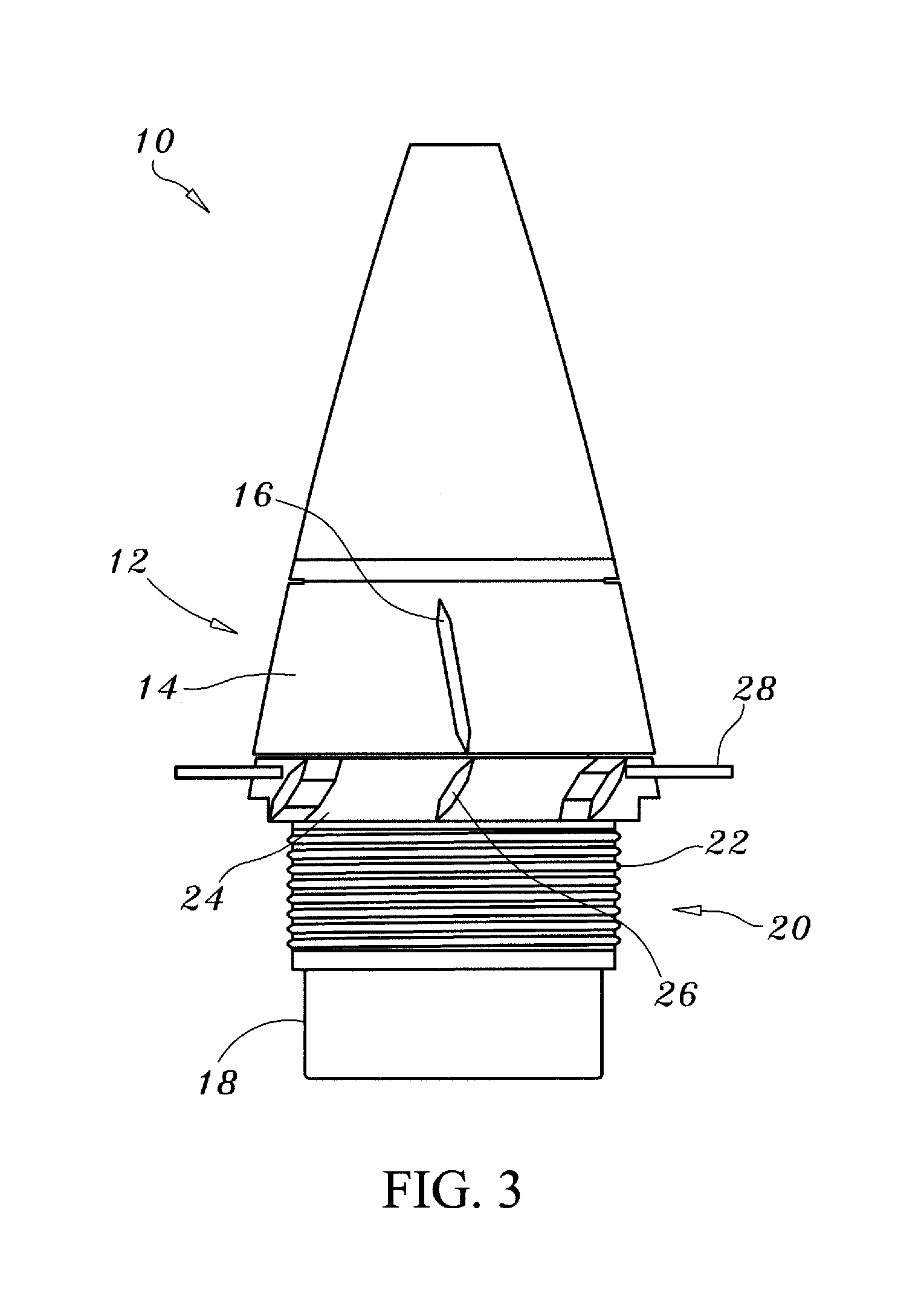
[0037]One embodiment of the invention is shown in FIGS. 1-4. A projectile such as a 105 mm round incorporating the invention is shown generally at 10 in FIGS. 1 and 2. The RCD 12 includes a rotating guidance collar 14. The guidance collar may be located near a front end of the projectile 10 or near an aft end of the projectile. The collar 14 is rotatably attached to the projectile 10. The guidance collar 14 may have one or more externally mounted guidance collar aero-surfaces 16 such as strakes; however, other...


PUM


Abstract

The invention is a projectile, device and system having a roll control device which may be fixed or deployable, for providing torque counter to the spin of the projectile and providing drag on the projectile. The roll control device includes a guidance collar rotatably attached to the projectile located near a front end of the projectile wherein the guidance collar includes one or more guidance collar aero-surfaces shaped to provide torque counter to the spin on the projectile. The guidance collar aero-surfaces may be controlled by a brake and guidance electronics on the projectile. The invention also includes a body collar fixedly attached to the projectile aft of the guidance collar, wherein the body collar includes one or more body collar aero-surfaces and fixed or deployable drag devices. Another embodiment use only a guidance collar aero-surfaces to orient a fixed drag device relative to an Earth inertial reference frame to create asymmetrical drag on the projectile and thereby altering its trajectory.

Description

CROSS-REFERENCE TO RELATED APPLICATION[0001]This application relates to the same subject matter as co-pending provisional patent application Ser. No. 61 / 113,991, filed by the same applicant on Nov. 12, 2008. This application claims the Nov. 12, 2008 filing date as to the common subject matter.BACKGROUND OF THE INVENTION[0002]1. Field of the Invention[0003]The disclosure relates generally to projectiles and, more specifically, to an apparatus, method and system for controlling the spin and / or orienting the guidance section of a projectile.[0004]2. Description of the Related Art[0005]The optimization of two dimensional course correction for a projectile requires a solution that is effective, has low cost, weight and power consumption. This is true for the design of a new projectile as well as the retrofit of an existing one.[0006]One embodiment of this invention provides trajectory control by manipulation of the projectile's yaw of repose and manipulation of its drag allowing the effe...

Claims


Application Information

Patent Timeline
Patent Type & Authority Applications(United States)
IPC IPC(8): F42B15/01F42B10/26
CPCF42B10/62F42B10/54
Inventor MORRIS, JOSEPH P.SMITH, DOUGLAS L.
Owner GEN DYNAMICS ORDNANCE & TACTICAL SYST
Why Eureka
Try Eureka