Modular mould system for manufacturing a shell part

a technology of modular moulds and shell parts, applied in the field of modular mould systems, can solve the problems of enhancing problems, occupying space in the manufacture of large oblong composite structures, etc., and achieve the effects of reducing manufacturing tolerances, improving the finish surface of shell parts, and being easy to manufactur

a technology of modular moulds and shell parts, applied in the field of modular mould systems, can solve the problems of enhancing problems, occupying space in the manufacture of large oblong composite structures, etc., and achieve the effects of reducing manufacturing tolerances, improving the finish surface of shell parts, and being easy to manufactur

US20120211637A1Active Publication Date: 2012-08-23LM GLASSFIBER

Image

  • Modular mould system for manufacturing a shell part
  • Modular mould system for manufacturing a shell part
  • Modular mould system for manufacturing a shell part

Examples


Embodiment Construction

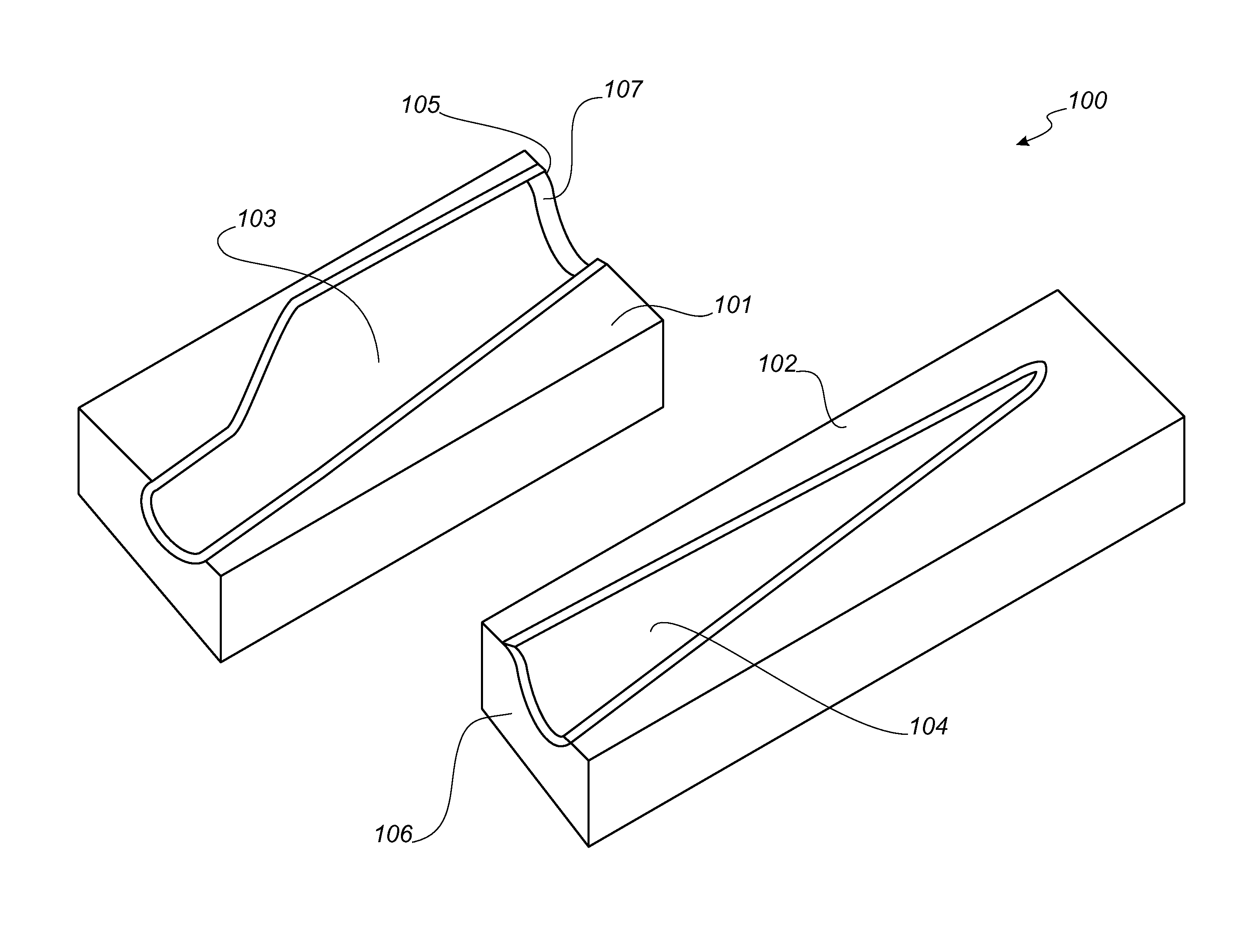
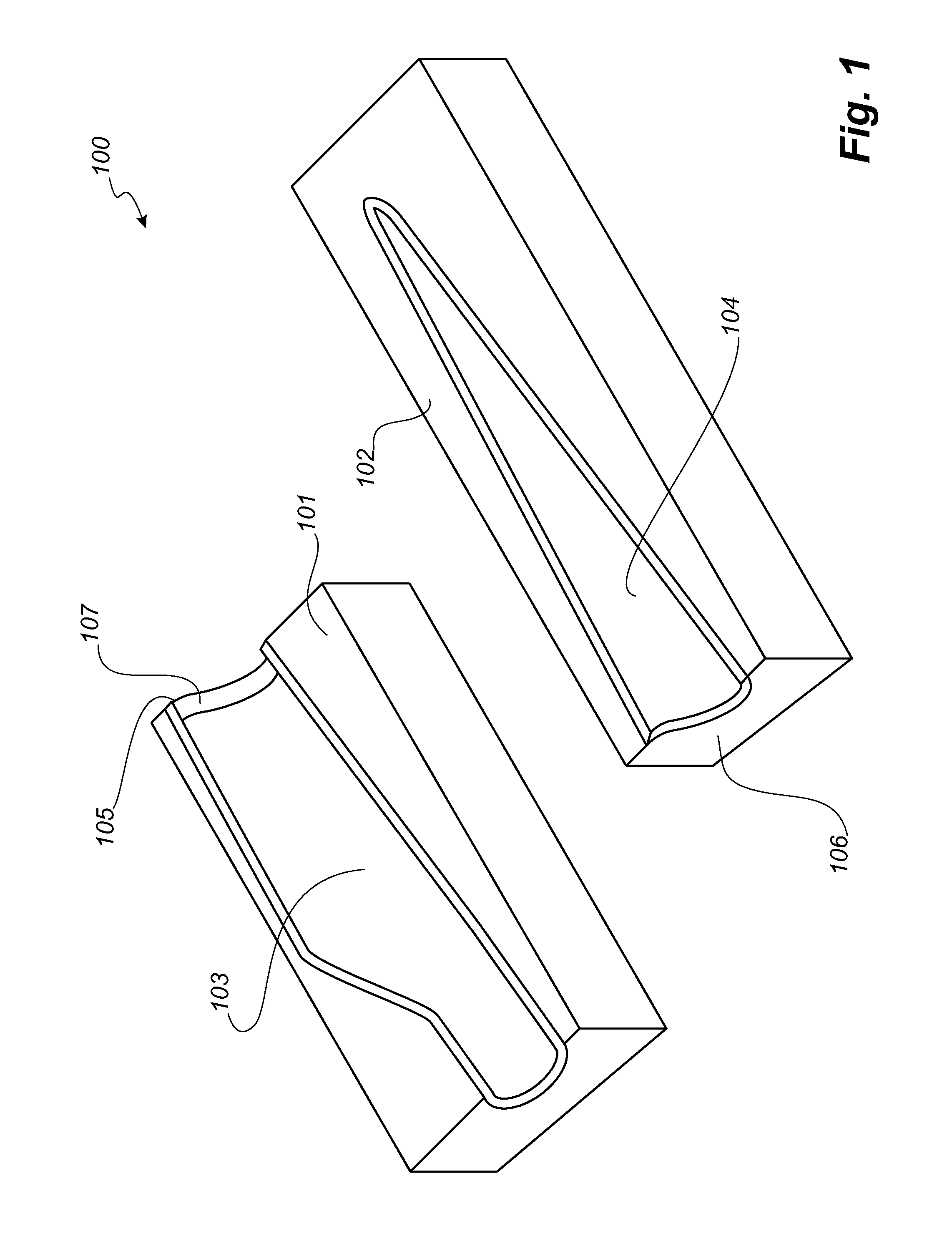
[0054]FIG. 1 illustrates a modular mould part 100 according to the inventive system. Here, the mould part 100 is shown to comprise two mould sections, namely the first 101 and the second 102 mould section. When assembled, the two mould sections 101, 102 form an assembled mould part. Assembly of the two mould sections 101, 102 is accommodated by the end section 105 of the first mould section 101 and the end section 106 of the second mould section 102. At least the end section 105 of the first mould section 101 comprises an end segment 107, which is at least flexible in parts. The end section 106 of the second mould section 102 may also comprise a partly flexible end segment (not shown).

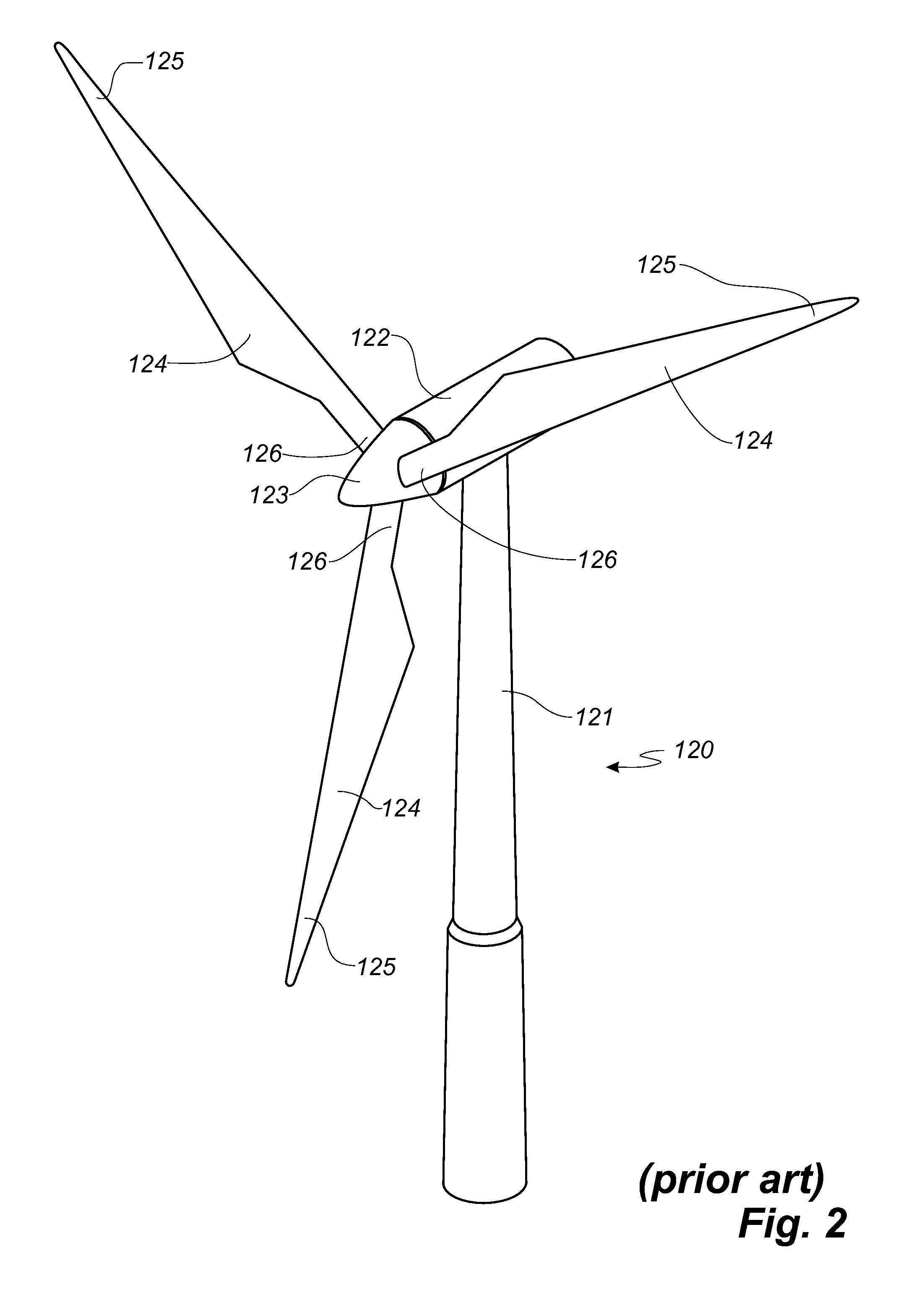
[0055]FIG. 2 illustrates a conventional modern upwind wind turbine 120 according to the so-called “Danish concept” with a tower 121, a nacelle 122 and a rotor with a substantially horizontal rotor shaft. The rotor includes a hub 123 and three blades 124 extending radially from the hub 123, each blade 1...


PUM

PropertyMeasurementUnit
lengthaaaaaaaaaa
lengthaaaaaaaaaa
flexibleaaaaaaaaaa

Abstract

A modular mould system for manufacturing a shell part of an oblong composite structure having a longitudinal direction from a fibre reinforced matrix material. The modular mould system includes a number of mould sections, which are adapted to being assembled to an assembled mould part. The number of mould sections includes a first mould section having a first moulding surface with a contour that defines a surface of a first longitudinal part of the shell part and a first end section; and a second mould section having a second moulding surface with a contour that defines a surface of a second longitudinal part of the shell part and a second end section; which, when the modular mould system is assembled to the assembled mould, the second end section of the second mould section abuts the first end section of the first mould section.

Description

TECHNICAL FIELD[0001]The present invention relates to a modular mould system for manufacturing a shell part of an oblong composite structure, the structure comprising a fibre reinforced matrix material and having a longitudinal direction, the mould system including a number of mould sections, which are adapted to being assembled to an assembled mould part, the number of mould sections comprising at least: a first mould section for moulding a first longitudinal part of the shell part and having a first moulding surface with a contour that defines a surface of the first longitudinal part of the shell part, the first mould section comprising an end section, and a second mould section for moulding a second longitudinal part of the shell part and having a second moulding surface with a contour that defines a surface of the second longitudinal part of the shell part, the second mould section comprising an end section, which, when the modular mould system is assembled to the assembled moul...

Claims


Application Information

Patent Timeline
23 Aug 2012
Publication
US20120211637A1
IPC
B41B11/62
CPC
B29C33/306; B29L2031/082; B29L2031/085; B29C33/302; B29C33/305; B29C33/005; B29C33/3842; Y02P70/50
Inventors
CHRISTIANSEN, PER KJAER; JOHANSEN, FINN