System and method for identifying non-cooperative pulsed radiation sources in a field-of-view of an imaging sensor

a non-cooperative, imaging sensor technology, applied in the direction of optical radiation measurement, photometry using electric radiation detectors, instruments, etc., can solve the problems of increased camera weight and power consumption, problems and other operational limitations of field and other military personnel, and achieve the effect of less weight, less energy consumption, and increased field of view

Active Publication Date: 2012-08-23
DRS NETWORK & IMAGING SYST
View PDF4 Cites 16 Cited by
  • Summary
  • Abstract
  • Description
  • Claims
  • Application Information

AI Technical Summary

Benefits of technology

[0005]To detect and determine characteristics of pulsed radiation sources, a system that uses an imaging sensor for sensing pulsed radiation sources and processes image data captured by the imaging sensor is provided. By using the imaging sensor ra

Problems solved by technology

The inclusion of a separate sensor from an imaging sensor results in increased camera weight and power consumption, both of which are valuable commodities for field personnel.
The single sensor typically has a very narrow field-of-view, general

Method used


Image

  • System and method for identifying non-cooperative pulsed radiation sources in a field-of-view of an imaging sensor
  • System and method for identifying non-cooperative pulsed radiation sources in a field-of-view of an imaging sensor
  • System and method for identifying non-cooperative pulsed radiation sources in a field-of-view of an imaging sensor

Examples


Embodiment Construction

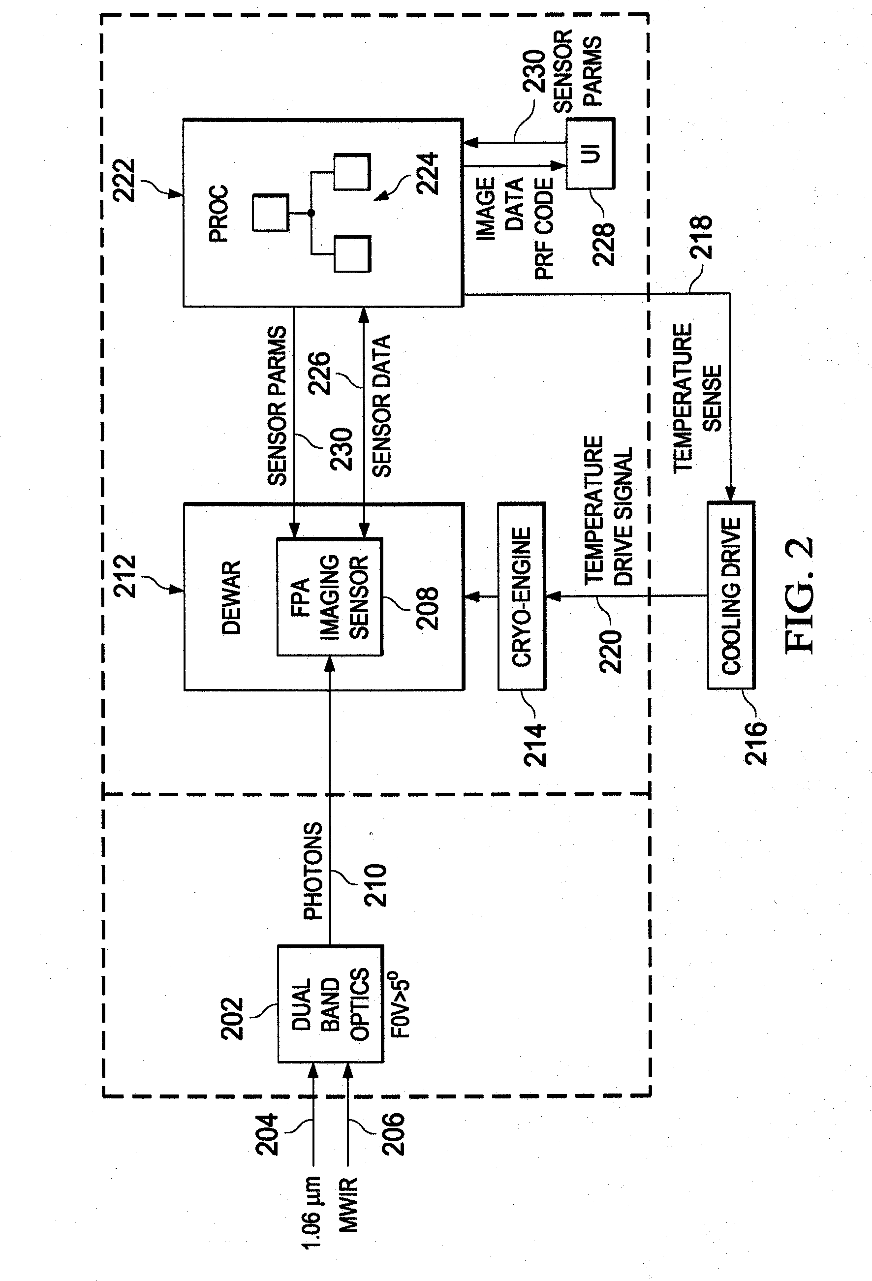
[0029]With regard to FIG. 2, a block diagram of electronic components of an illustrative camera 200 is shown. The camera 200 may be configured to record imaging data of a scene in one or more bands of optical or non-optical frequencies. The term “camera” may be used to describe an electro-optical system that collects or does not collect image data, such as binoculars, telescopes, or any other system that is configured to identify characteristics of pulsed radiation sources. The characteristics of the pulsed radiation sources may include pulse repetition frequency codes of pulsed radiation sources to identify a type of pulsed radiation source that is illuminating a target or other object. The camera 200 may include dual-band optics 202 that are configured to receive an optical signal 204, such as that in the 1.06 micrometer range, and midwave infrared frequency (MWIF) signal 206. In one embodiment, the dual band-optics 202 are configured to provide a field-of-view that is greater tha...


PUM


Abstract

A system and method for identifying a pulsed radiation source may include an imaging sensor having a frame rate that is less than a pulse repetition frequency (PRF) of the pulsed radiation source. A processing unit may be in communication with the imaging sensor, and be configured to (i) process a sequence of image data of a scene captured by the imaging sensor to determine whether radiation of the pulsed radiation source is detected, (ii) determine a PRF code of the pulsed radiation source from possible multiple different PRF codes based on the processed sequence of image data, and (iii) notify a user of the PRF code or information associated with the PRF code.

Description

BACKGROUND[0001]As military systems developers have increasingly improved precision of weapons and surveillance systems, the use of pulsed energy or radiation sources has been a key component in achieving improved precision. Generally speaking, pulsed radiation sources include lasers that operate with a given pulse rate and pulse width. Different pulsed radiation sources use different pulse rates and pulse widths.[0002]Military personnel, whether acting offensively or defensively, utilize sensing equipment to assist with offensive and defensive military operations. From an offensive perspective, one operation for which military personnel use sensing equipment is to monitor targets that are being targeted by remote pulsed radiation sources to ensure the correct target is being illuminated. Targets are generally illuminated by pulsed radiation sources either by the weapons system itself or personnel on the ground for the weapons system to target. From a defensive perspective, one oper...

Claims


Application Information

Patent Timeline
IPC IPC(8): G01T1/17
CPCG01S7/4804F41G7/2293F41G7/226F41G3/145
Inventor CLOUD, EUGENE L.RAKES, ALANBAILEY, JOHN
Owner DRS NETWORK & IMAGING SYST
Why Eureka
Try Eureka