Laser cutting method

a cutting method and laser cutting technology, applied in the direction of glass making apparatus, manufacturing tools, welding/soldering/cutting articles, etc., can solve the problems of score-and-break process, inability to consistently and reliably produce glass sheets with high-quality edges, and pre-formed initiation defects on glass to propagate into a score-line with a given depth, etc., to achieve easy production, reduce the number of process steps, and simplify the cutting process

Active Publication Date: 2012-08-23
CORNING INC
View PDF9 Cites 64 Cited by
  • Summary
  • Abstract
  • Description
  • Claims
  • Application Information

AI Technical Summary

Benefits of technology

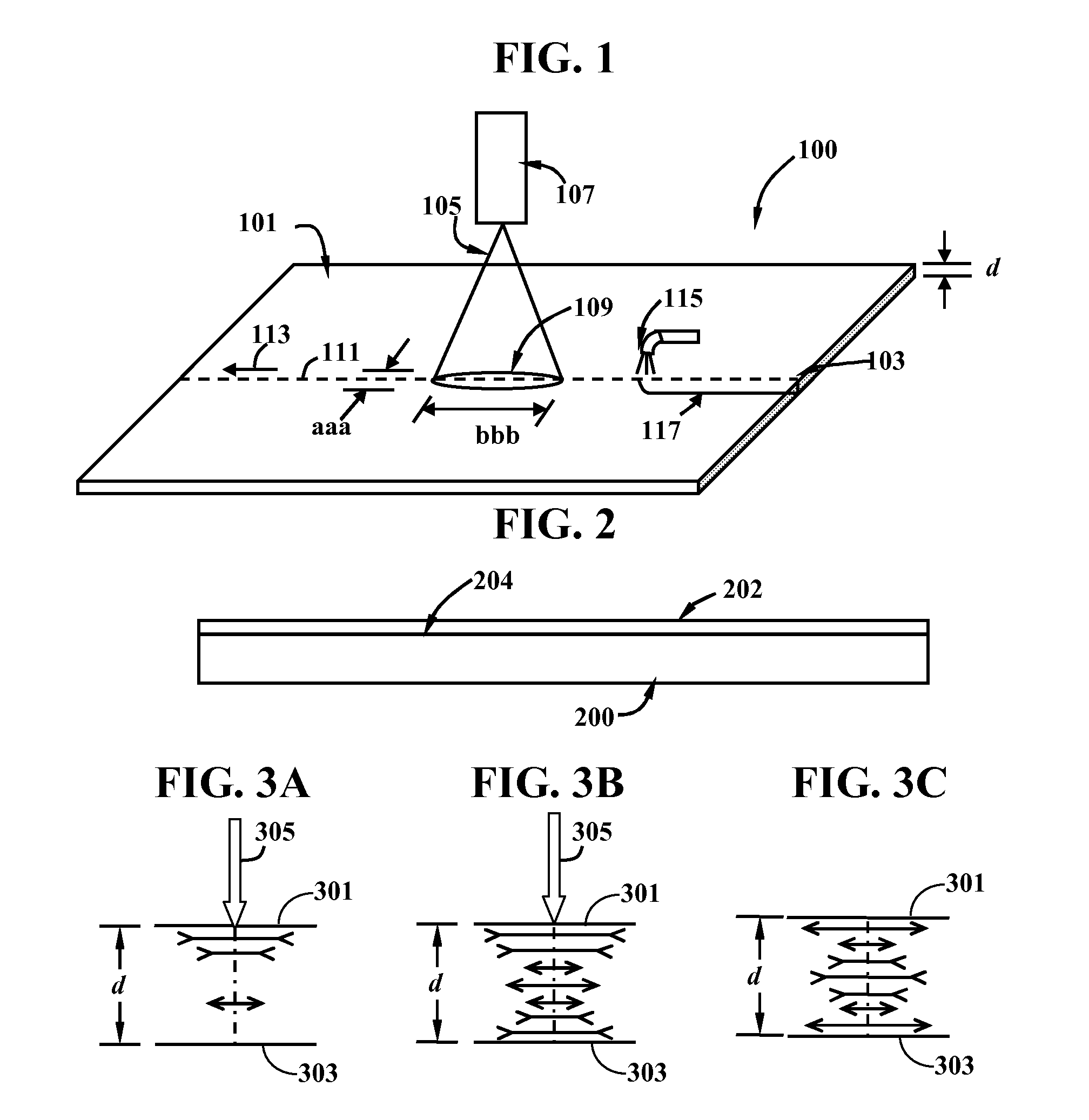
[0081]One or more embodiments of the present invention have one or more of the following advantages. First, because of the full-body cutting effect, the invention reduces the number of process steps in the process, thereby significantly simplifies the cutting process compared to score-and-break processes. Second, the inventive method enables free-shape cutting of thin sheets with non-linear edges. For example, rectangular pieces of sheets with round corners, which are more shatter-resistant than those with right angle corners, can be easily produced using the inventive method. Third, due to the ability to precisely control the scanning path geometry and dimension, one can use the inventive process for cutting sheets on which devices sensitive and vulnerable to exposure to high temperature, such as transistors, wires, optical devices, along predetermined paths at a relatively small distance from those devices, without overheating the adjacent devices. In addition, with respect to the first aspect of the present invention, another advantage is the capability of cutting pieces from a mother sheet, such as a glass sheet, with superior edge quality.

Problems solved by technology

Normally, a cooling fluid jet, such as water jet or air jet, is then applied to the heated surface, causing a tensile stress, which, if significant enough, can cause a pre-formed initiation defect on the glass to propagate into a score-line with a given depth.
It has been found that, for glass sheets with such thin thicknesses, the score-and-break process, whether involving a laser scoring or mechanical scoring step, cannot be utilized to consistently and reliably produce glass sheets with high-quality edges.
However, reliability and edge quality of those processes need further improvement.
In addition, those processes can be very complex.

Method used


Image

  • Laser cutting method
  • Laser cutting method
  • Laser cutting method

Examples


examples

[0144]The following non-limiting examples further illustrate the present invention.

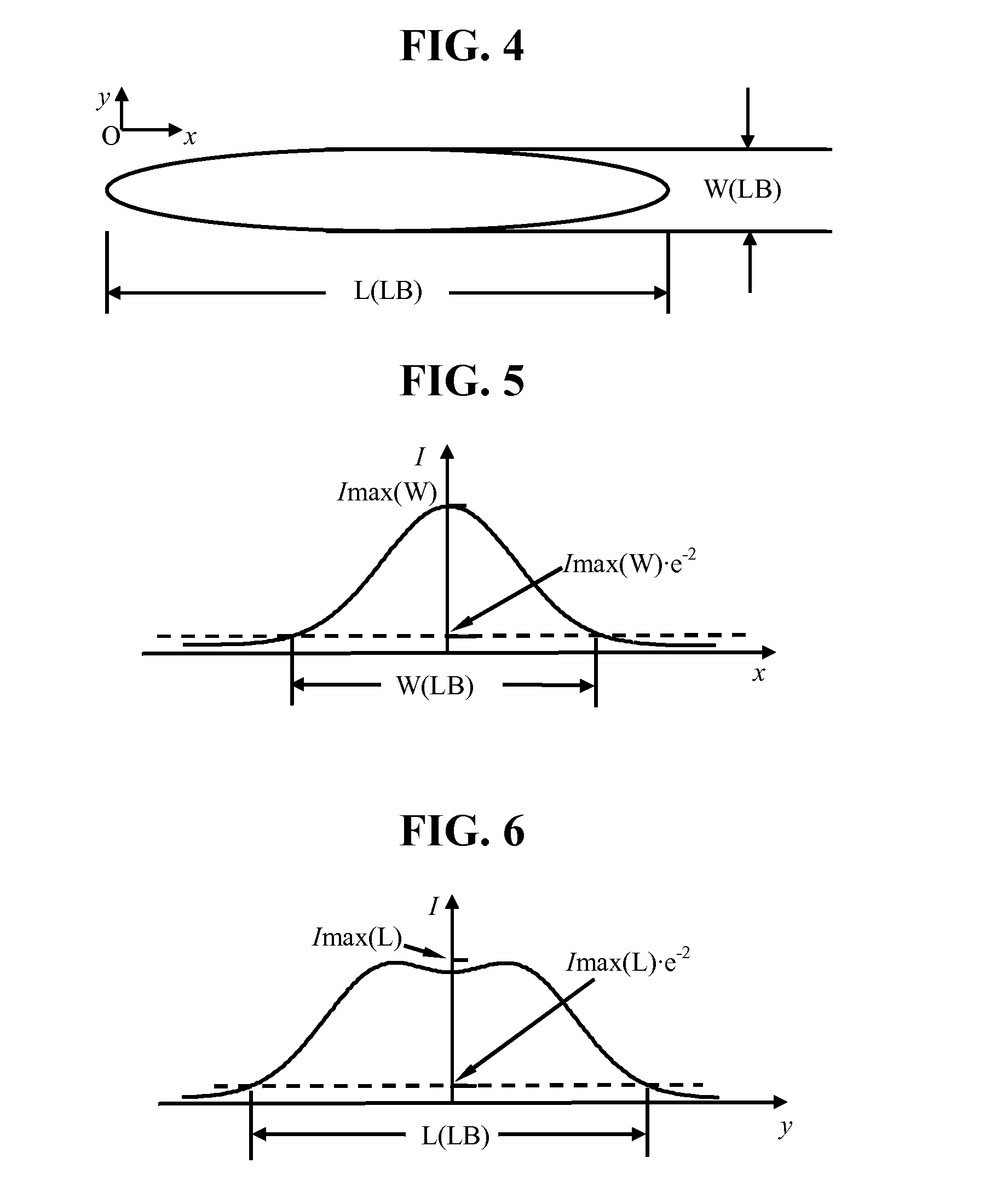
[0145]Redrawn glass sheet with different glass thickness (100 μm, and 200 μm) were cut with the fast scanning circular CO2 laser beam cutting method. The laser beam was line scanned over a length of ˜200 mm with a scanning speed of 20,000 mm / s. The defocused laser beam has a diameter of ˜1 mm and an average power density of about 18 W·cm−2. Cut glass sheet samples, with a width of 20 mm and a length of 100 mm, was tested with the 2-point bending method for strength in terms of failure stress. FIG. 11 shows the Weibull plot of the measured result from the 2-point bending method. The minimum failure stress of the test specimens was 120 MPa for redrawn glass having a thickness of 200 μm, and 160 MPa for redrawn glass having a thickness of 100 μm. In comparison, mechanically cut samples at thicker thickness (>0.3 mm) typically have an edge failure stress of ˜100 MPa in 4-point bending test. Thus, the thin...


PUM

PropertyMeasurementUnit
thicknessaaaaaaaaaa
distanceaaaaaaaaaa
speedaaaaaaaaaa

Abstract

A method for cutting a sheet of material having a thickness of at most 400 μm using an electromagnetic wave beam (EWB) such as a laser. The method comprises forming a surface initiation defect and irradiating the sheet along a predetermined path within a short distance from the initiation defect a scanning EWB, such that the sheet is heated and cooled to allow for the propagation of the initiation defect into the predetermined path, and further along the predetermined path to result in a separation of the sheet along the predetermined irradiation path. This method can be advantageously used to cut glass sheets having a thin thickness to result in high-quality edge substantially free of major defects carried over from the initiation defect.

Description

FIELD[0001]The present invention relates to methods for separating a sheet of brittle material. In particular, the present invention relates to methods for cutting a thin sheet of brittle material using an electromagnetic wave beam (EWB). The present invention is useful, e.g., in cutting thin glass sheets having a thickness not higher than 400 μm into desired shapes for use in display industries.TECHNICAL BACKGROUND[0002]Glass sheets have been used in the manufacture of display devices such as LCD TVs, computer monitors and handheld devices. For example, in a modern LCD TV set, a piece of thin glass sheet with pristine surface quality is used as a substrate for TFT and other electronic devices, and another piece is used as a substrate for the color filter. Recently, thin glass sheets started to find use as cover sheets for the screens of handheld devices and TV sets as well.[0003]The thin glass sheets are typically made by using a fusion down-draw process, which is pioneered by Corn...

Claims


Application Information

Patent Timeline
Patent Type & Authority Applications(United States)
IPC IPC(8): B23K26/38
CPCB23K26/0807B23K26/4075C03B33/091B23K26/421C03B33/04B23K26/408B23K26/082B23K26/40B23K26/60B23K2103/50B23K2103/52
Inventor GARNER, SEAN MATTHEWLI, XINGHUA
Owner CORNING INC
Why Eureka
Try Eureka