
Method and system controlling an electrical motor with temperature compensation

a technology of electrical motors and temperature compensation, which is applied in the direction of motor/generator/converter stoppers, dynamo-electric converter control, pulse technique, etc., can solve the problems of rotor magnet temperature being poorly defined, erratic or inconsistent relationship, and decreasing output torque and operating efficiency of the motor

Active Publication Date: 2012-08-23
DEERE & CO
View PDF1 Cites 57 Cited by
  • Summary
  • Abstract
  • Description
  • Claims
  • Application Information

AI Technical Summary

Benefits of technology

[0004]In accordance with one embodiment, the method and system for controlling an electrical motor comprises a rotor with associated rotor magnets and a stator. A temperature estimation module estimates a change in temperature of the magnets associated with the rotor of the motor based on an operational magnetic flux strength that is compared to a reference magnetic flux strength determined at a known ambient temperature and for a predetermined operating range of the motor. The temperature estimation module or the system establishes a relationship between the estimated change in the temperature and a magnetic torque component of a target output torque of the motor consistent with the predetermined operating range. The current adjustment module or the data processing system adjusts a command (e.g., quadrature-axis current command or the quadrant axis current) for the motor to compensate for shaft torque variation associated with the estimated change in the temperature in conformance with the established relationship.

Problems solved by technology

In turn, if the magnetic field strength decreases, the output torque and operating efficiency of the motor tends to decrease.
Further, the rotor magnet temperature may have a poorly defined, erratic or inconsistent relationship with the stator winding temperature or coolant temperature at different speed regions of the motor.

Method used


Image

  • Method and system controlling an electrical motor with temperature compensation
  • Method and system controlling an electrical motor with temperature compensation
  • Method and system controlling an electrical motor with temperature compensation

Examples


Embodiment Construction

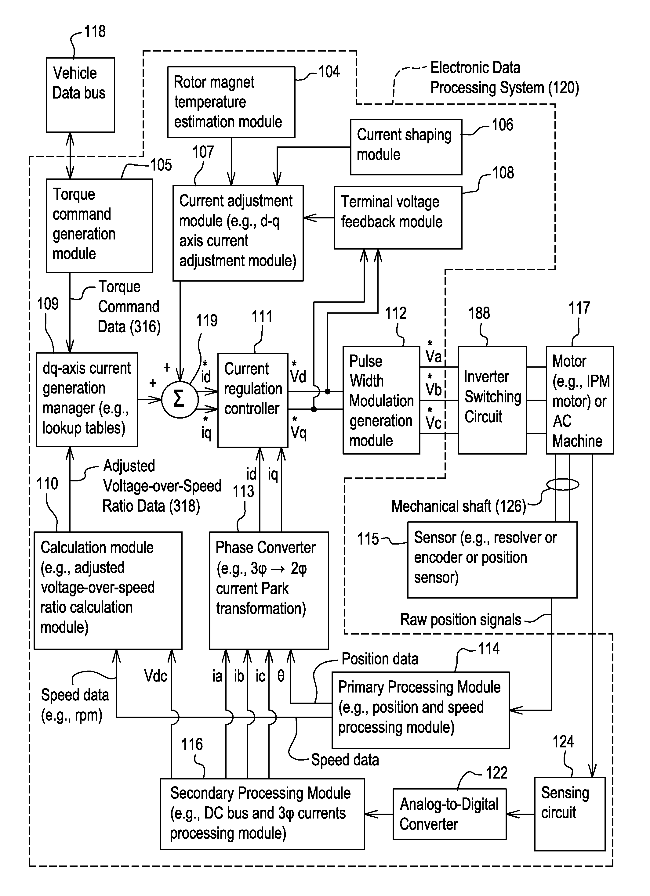
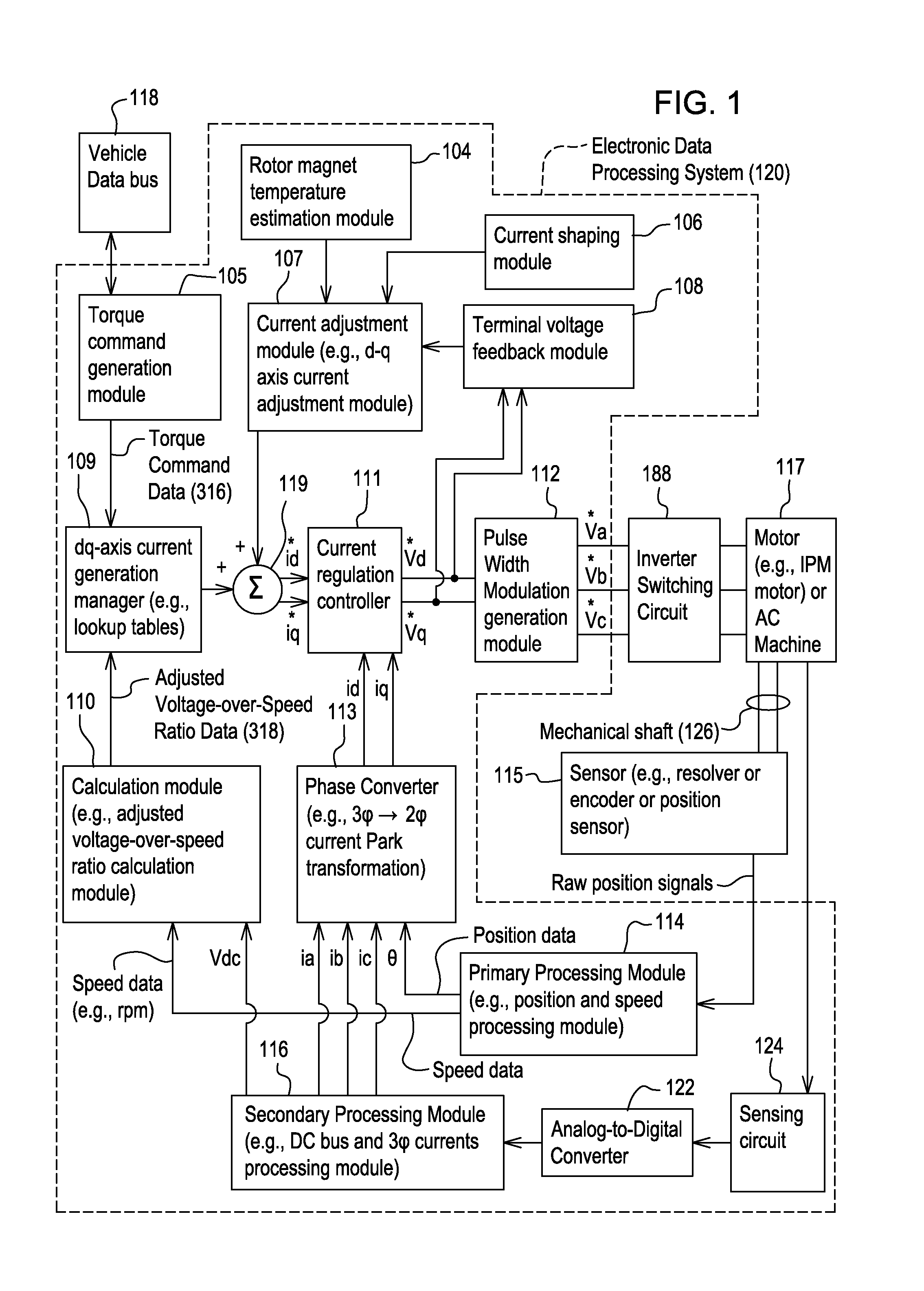
[0011]In accordance with one embodiment, FIG. 1 discloses system for controlling a motor 117 (e.g., an interior permanent magnet (IPM) motor) or another alternating current machine. In one embodiment, the system, aside from the motor 117, may be referred to as an inverter or a motor controller.

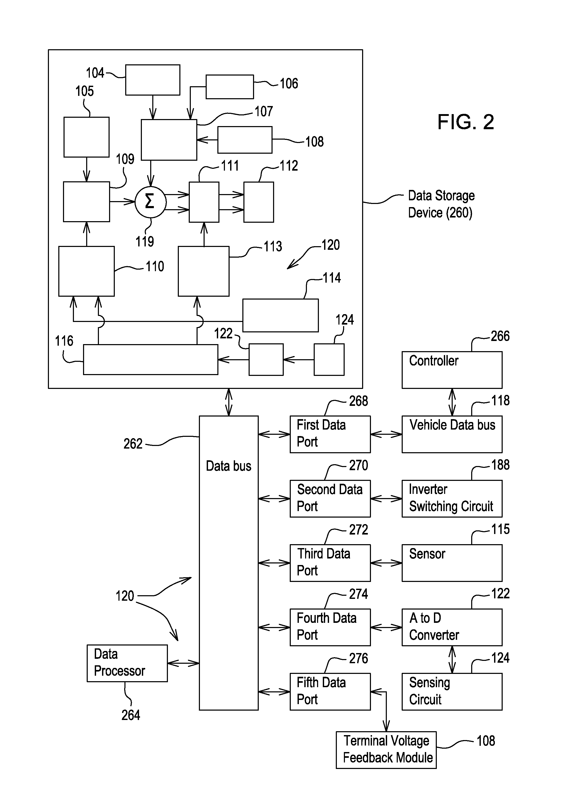
[0012]The system comprises electronic modules, software modules, or both. In one embodiment, the motor controller comprises an electronic data processing system 120 to support storing, processing or execution of software instructions of one or more software modules. The electronic data processing system 120 is indicated by the dashed lines in FIG. 1 and is shown in greater detail in FIG. 2.

[0013]The data processing system 120 is coupled to an inverter circuit 188. The inverter circuit 188 comprises a semiconductor drive circuit that drives or controls switching semiconductors (e.g., insulated gate bipolar transistors (IGBT) or other power transistors) to output control signals for the motor 11...


PUM


Abstract

A temperature estimation module estimates a change in temperature of the magnets associated with the rotor of the motor based on an operational magnetic flux strength that is compared to a reference magnetic flux strength determined at a known ambient temperature and for a predetermined operating range of the motor The temperature estimation module or the system establishes a relationship between the estimated change in the temperature and a magnetic torque component of a target output torque of the motor consistent with the predetermined operating range. The current adjustment module or the system adjusts a command (e.g., quadrature-axis current command) for the motor to compensate for shaft torque variation associated with the estimated change in the temperature in conformance with the established relationship.

Description

[0001]This document claims priority based on U.S. provisional application Ser. No. 61 / 445,650, filed on 23 Feb. 2011 and entitled METHOD AND SYSTEM CONTROLLING AN ELECTRICAL MOTOR WITH TEMPERATURE COMPENSATION, under 35 U.S.C. 119(e).FIELD OF THE INVENTION [0002]This invention relates to a method and system for controlling an electrical motor with temperature compensation.BACKGROUND OF THE INVENTION[0003]An electric motor may feature a rotor with permanent magnets and a stator, such as an interior permanent magnet (IPM) motor or IPM synchronous motor. An interior permanent magnet (IPM) motor or IPM synchronous machine may have varying magnetic field strength because of a temperature change in the magnets associated with the rotor. In turn, if the magnetic field strength decreases, the output torque and operating efficiency of the motor tends to decrease. Certain motors have no direct temperature sensors that measure the temperature of the magnets on the rotor, as opposed to the stat...

Claims


Application Information

Patent Timeline
Patent Type & Authority Applications(United States)
IPC IPC(8): H02P7/285
CPCH02P7/285H02P21/141H02P29/662
Inventor WU, LONGSHAW, ROBERT
Owner DEERE & CO
Learn More