Vacuum cleaning structure for electrode furnace

a vacuum cleaning and electrode furnace technology, applied in furnaces, furnace types, furnace heating elements, etc., can solve the problems of contaminated enclosed furnace chambers, dust, soot, etc., and achieve the effect of improving cleaning quality and increasing airflow turbulen

Active Publication Date: 2012-08-23
LECO CORPORATION
View PDF21 Cites 13 Cited by
  • Summary
  • Abstract
  • Description
  • Claims
  • Application Information

AI Technical Summary

Benefits of technology

[0005]The system of this invention provides an improved electrode and electrode cleaning manifold which is positioned on the electrode to increase the airflow turbulence for removal of dust and debris during cleaning of an analytical furnace. One embodiment of the invention is an electrode for engaging a crucible, which electrode has an end spaced from the crucible-engaging surface with a plurality of grooves formed therein, allowing cleaning air to flow through the grooves. In another embodiment, a manifold for fitting over the end of the electrode is provided to provide a dust recovery plenum. An outlet communicating with the plenum is coupled to a vacuum source to remove debris from the furnace and electrode. Systems embodying the present invention include an electrode having an end with a plurality of curved grooves formed therein and a manifold, which fits over the end of the electrode. The manifold defines a dust recovery plenum coupled to an outlet for coupling to a vacuum source to remove debris from the furnace and electrode. In a further embodiment, the system also includes an abrading brush used concurrently with the dust removing vacuum source.
[0006]With these improvements, the analytical furnace can be frequently cleaned and the quality of cleaning improved. These and other features, objects and advantages of the present invention will become apparent upon reading the following description thereof together with reference to the accompanying drawings.

Problems solved by technology

During the heating of a specimen, the enclosed furnace chamber becomes contaminated with debris, dust, soot, and the like from the byproducts of fusing the sample and needs to be frequently cleaned.

Method used


Image

  • Vacuum cleaning structure for electrode furnace
  • Vacuum cleaning structure for electrode furnace
  • Vacuum cleaning structure for electrode furnace

Examples


Embodiment Construction

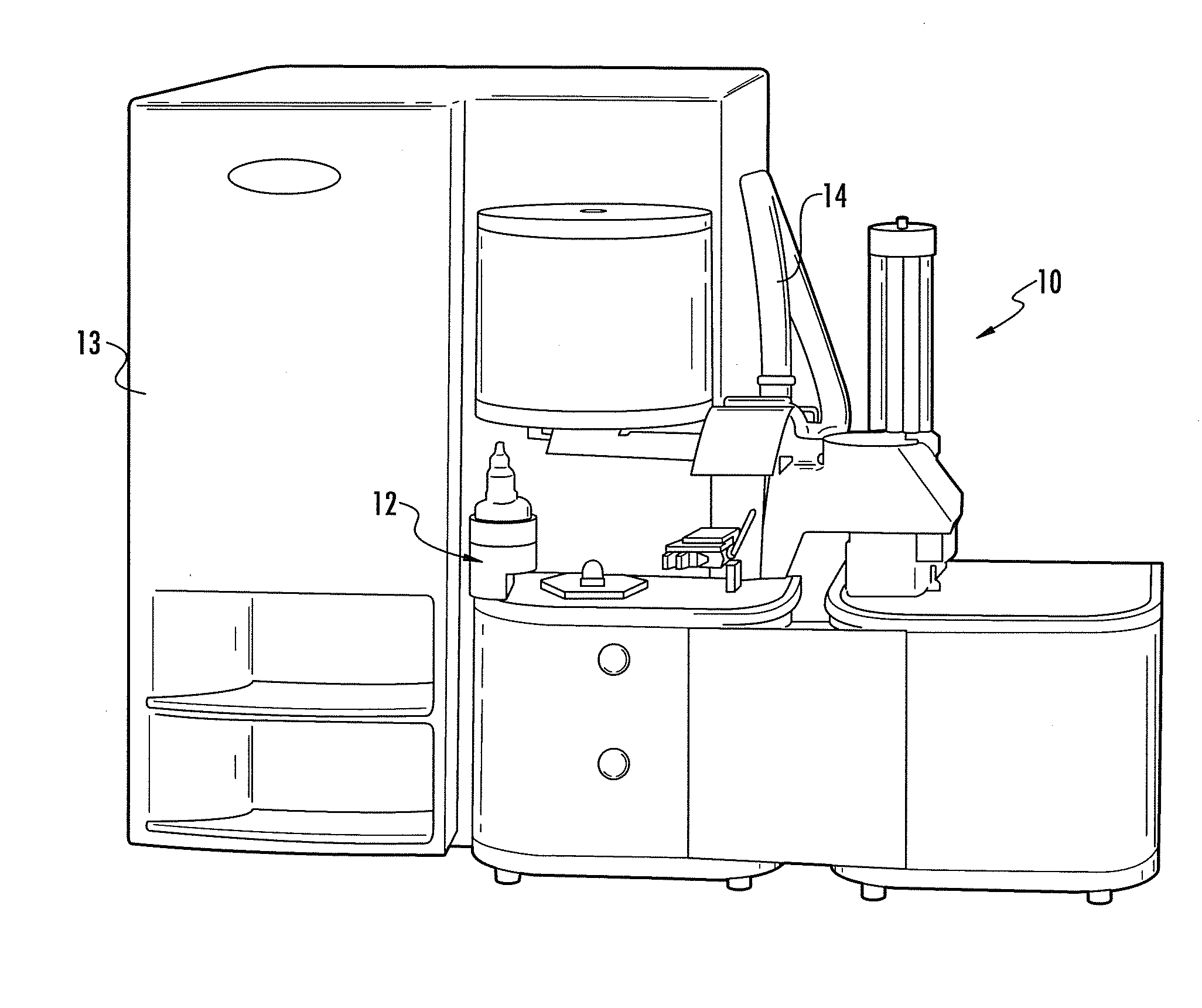
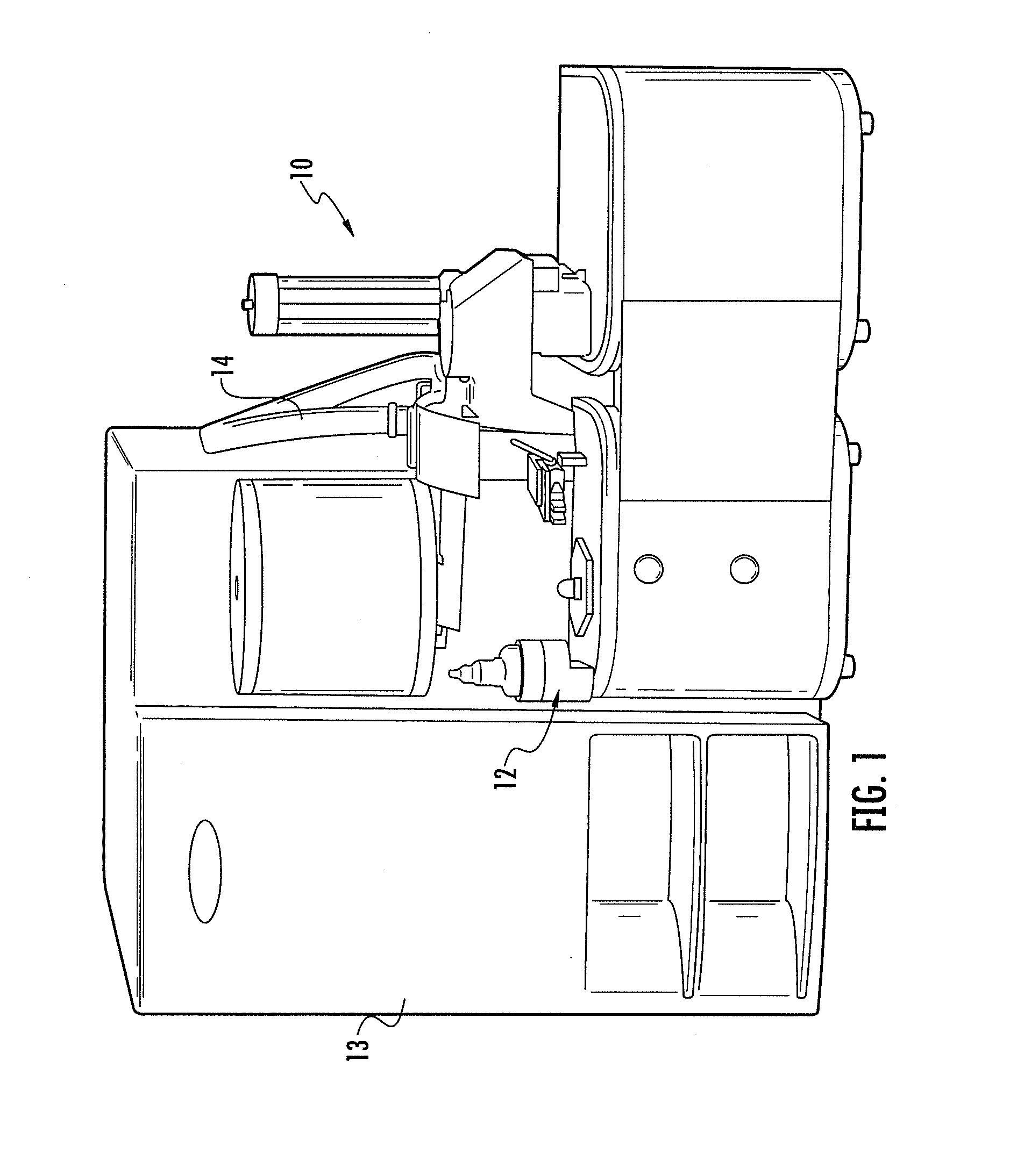
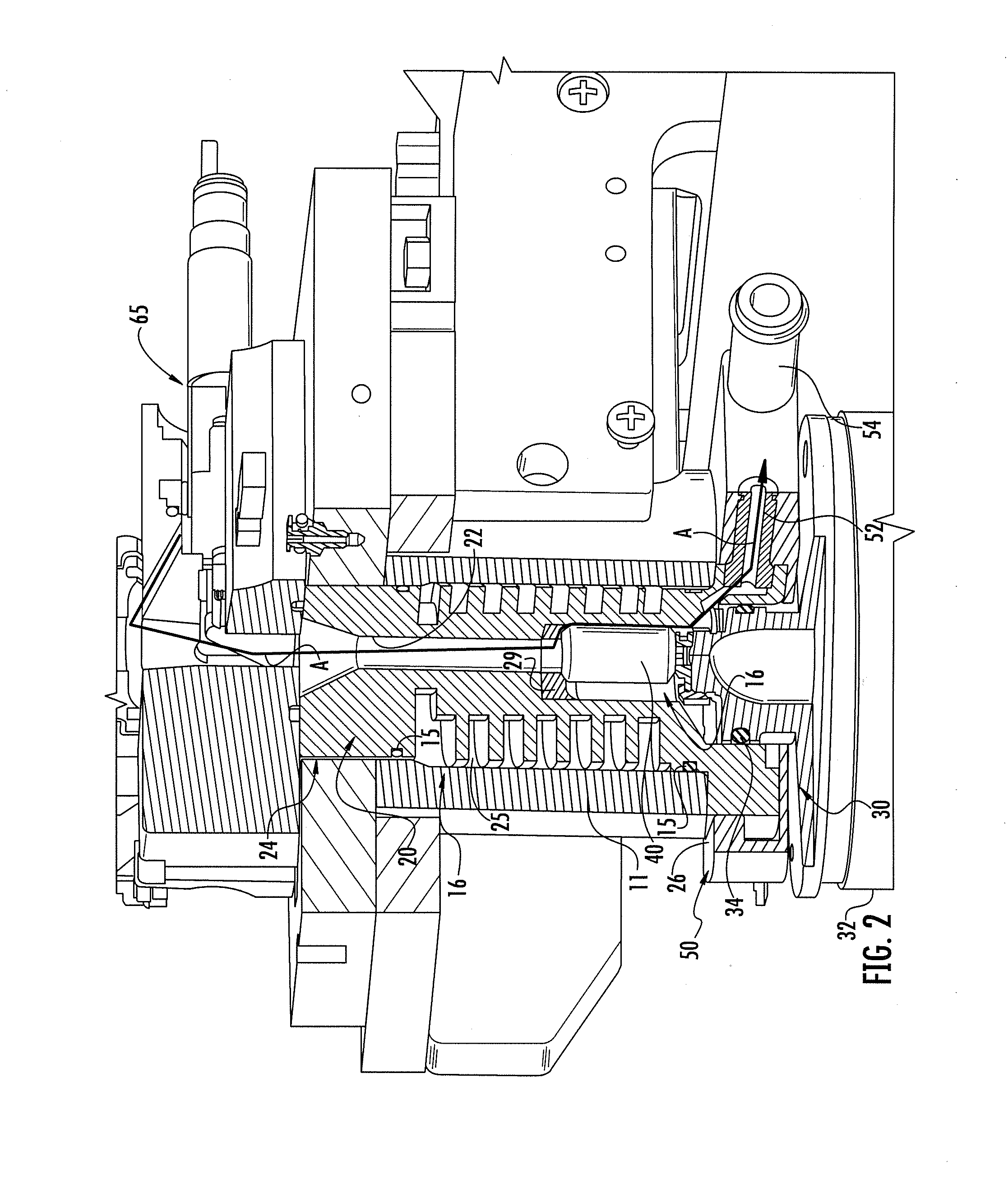
[0021]Referring initially to FIG. 1, there is shown an analytical instrument 10, such as a Model ONH836 nitrogen, oxygen, hydrogen analyzer, commercially available from Leco Corporation of St. Joseph, Mich. The instrument is designed to incorporate the present invention and includes a resistance furnace 16, as best seen in FIG. 2. The furnace includes an upper electrode 20 incorporating one aspect of the present invention and a lower electrode 30 which sealably encloses the furnace chamber within the upper electrode and engages a graphite crucible 40 positioned between the upper and lower electrodes. A suitable power supply is conventionally coupled to the upper and lower electrodes to pass sufficient current through crucible 40 to heat a sample specimen contained therein to a temperature of 2500° C. or higher to release analyte gases from the sample. As is well known, a supply of inert carrier gas, such as helium, flows downwardly through the central opening 22 of upper electrode 2...


PUM


Abstract

An electrode for a resistance analytical furnace has a crucible-engaging surface and an end spaced from the crucible-engaging surface having a plurality of grooves formed therein. A manifold mounted on the end of the electrode defines a dust recovery plenum and includes an outlet communicating with the plenum for coupling to a vacuum source to remove debris from the electrode. The improved electrode and electrode cleaning manifold positioned on the electrode provides a turbulent airflow for removal of dust and debris from an analytical furnace.

Description

CROSS-REFERENCE TO RELATED APPLICATIONS[0001]This application claims priority under 35 U.S.C. §119(e) and the benefit of U.S. Provisional Application No. 61 / 444,294, entitled VACUUM CLEANING INTERFACE FOR ELECTRODE FURNACE, filed on Feb. 18, 2011, by Octavio R. Latino, et al., the entire disclosure of which is incorporated herein by reference.BACKGROUND OF THE INVENTION[0002]The present invention relates to analytical furnaces and particularly to an improved electrode and vacuum system for cleaning the electrodes and furnace area of a resistance furnace.[0003]Analytical furnaces heat specimens, such as chips and pin samples, and the like, typically ranging in mass of about 1 gram or less in a crucible. Resistance furnaces employ graphite crucibles clamped between two electrodes which pass an electrical current through the crucible, heating specimens to temperatures of 2500° C. or higher. The gaseous byproducts of fusing the specimen are then swept by an inert gas through the furnace...

Claims


Application Information

Patent Timeline
Patent Type & Authority Applications(United States)
IPC IPC(8): H05B3/62
CPCH05B3/62G01N31/12F27B17/02
Inventor LATINO, OCTAVIO R.FORD, GORDON C.ALLEN, LLOYD A.
Owner LECO CORPORATION
Why Eureka
Try Eureka